Page 7.1 - 8 COMBIVERT F5-A, -E, -H © KEB, 2012-10
Operating and appliance data
Parameter Addr. R PG E Min. value Max. value Res. [?] Default
ru.22 internal input state 0216h RO - - 0 4095 1 - -
Display of the digital external and internal inputs set currently. The input is only regarded as set if it is available
as effective signal to the further processing (i.e. accepted through strobe, edge-triggering or logic operation).
According to table like ru.21 a specic decimal value is given out for each digital input. If several inputs are
controlled, the sum of the decimal values (see ru.21) is indicated (also see Chapt. 7.3 „Digital inputs“).
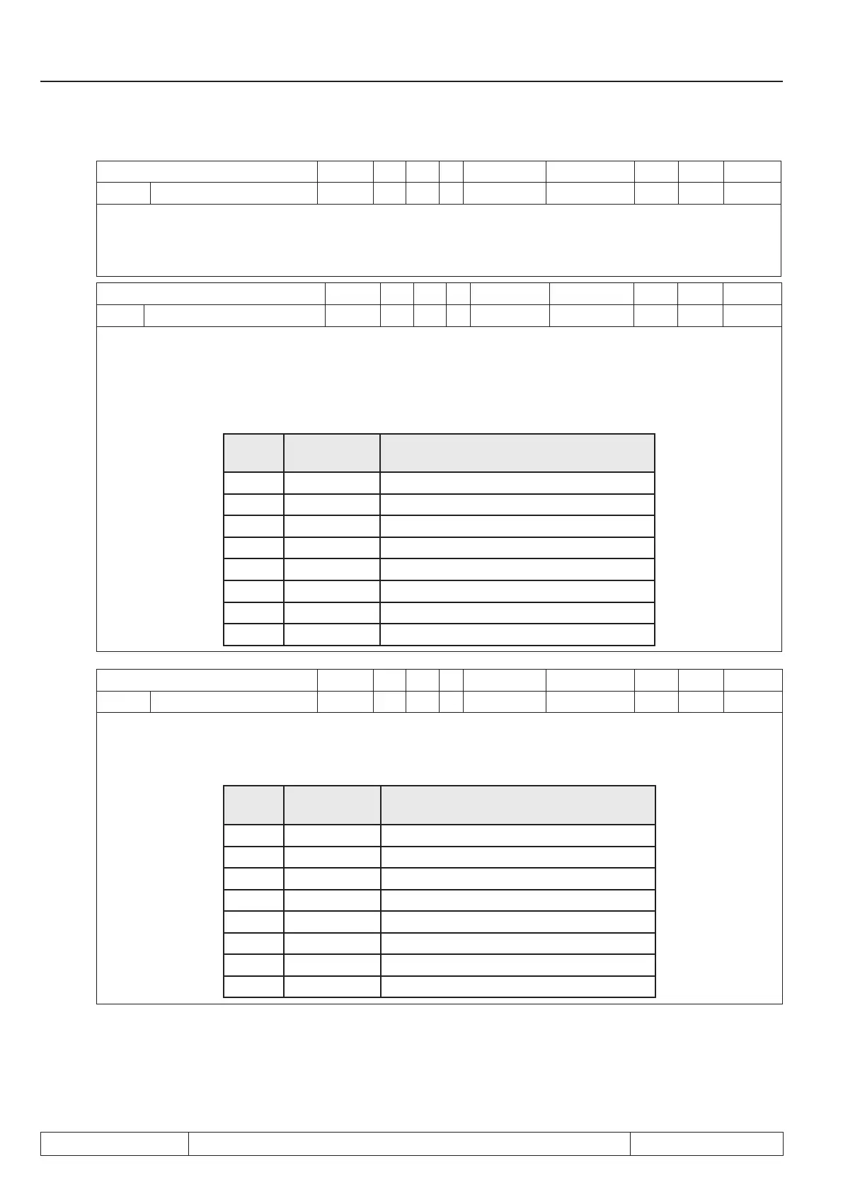
Parameter Addr. R PG E Min. value Max. value Res. [?] Default
ru.23 output condition state 0217h RO - - 0 255 1 - -
With parameters do.0...do.7 switching conditions can be selected, that serve as a base for setting the outputs.
This parameter indicates which of the selected switching conditions are met before they are linked or inverted
by programmable logic (also see Chapt. 7.3. „Digital outputs“). According to following table a specic decimal
value is given out for the switching conditions. If several of the selected switching conditions are met, the sum
of the decimal values is indicated.
Bit
-No.
Decimal
value
Output
0 1 Switching condition 0 (do.0)
1 2 Switching condition 1 (do.1)
2 4 Switching condition 2 (do.2)
3 8 Switching condition 3 (do.3)
4 16 Switching condition 4 (do.4)
5 32 Switching condition 5 (do.5)
6 64 Switching condition 6 (do.6)
7 128 Switching condition 7 (do.7)
Parameter Addr. R PG E Min. value Max. value Res. [?] Default
ru.24 State of output ags 0218h RO - - 0 255 1 - -
Display of the output ags after logic step 1. The selected switching conditions are linked in logic step 1
(do.08...24) and indicated here (see chapt. 7.3 „Digital outputs“). According to following table a specic decimal
value is given out for any output ags. If several output ags are set, the sum of the decimal values is indicated.
Bit
-No.
Decimal
value
Output
0 1 Flag 0
1 2 Flag 1
2 4 Flag 2
3 8 Flag 3
4 16 Flag 4
5 32 Flag 5
6 64 Flag 6
7 128 Flag 7

 Loading...

