Operating and appliance data
© KEB, 2012-10 COMBIVERT F5-A, -E, -H Page 7.1 - 9
7
Parameter Addr. R PG E Min. value Max. value Res. [?] Default
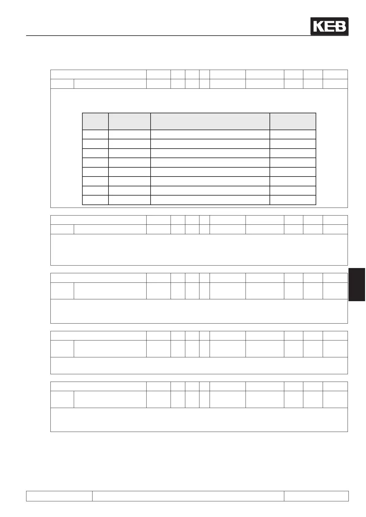
ru.25 output terminal state 0219h RO - - 0 255 1 - -
Display of the external and internal digital outputs set currently. According to following table a specic decimal
value is given out for each digital output. If several outputs are set, the sum of the decimal values is indicated.
Bit
-No.
Decimal
value
Output Terminal
0 1 O1 (transistor output 1) X2A.18
1 2 O2 (transistor output 2) X2A.19
2 4 R1 (relay RLA,RLB,RLC) X2A.24...26
3 8 R2 (relay FLA,FLB,FLC) X2A.27...29
4 16 OA (internal output A) no
5 32 OB (internal output B) no
6 64 OC (internal output C) no
7 128 OD (internal output D) no
Parameter Addr. R PG E Min. value Max. value Res. [?] Default
ru.26 active parameter set 021Ah RO - - 0 7 1 - -
The KEB COMBIVERT can have access to 8 parameter sets (0-7). Through programming the inverter can
change parameter sets autonomously and can thus start different modes of operation. This parameter shows
the parameter set, with which the inverter is operating currently. Independent of it another parameter set can
be edited by bus (also see chapter 7.16).
Parameter Addr. R PG E Min. value Max. value Res. [?] Default
ru.27 AN 1 / pre amplier
display
021Bh RO - - -100 100 0.1 % -
This parameter indicates the value in percent of the analog signal AN1 on the differential voltage input (ter-
minal X2A.1 / X2A.2) before signal amplication. In dependence on An.10 the indicated value of 0...±100 %
corresponds to An.00: 0...±10 V; 0...±20 mA or 4...20 mA (also see chapt. 7.2 „Analog inputs“).
Parameter Addr. R PG E Min. value Max. value Res. [?] Default
ru.28 AN 1 / post amplier
display
021Ch RO - - -400 400 0.1 % -
This parameter shows the value of the analog signal AN1 in percent after passing the characteristic amplier.
The range of indication is limited to ±400 % (also see chapt. 7.2 „Analog inputs“).
Parameter Addr. R PG E Min. value Max. value Res. [?] Default
ru.29 AN 2 / pre amplier
display
021Dh RO - - -100 100 0.1 % -
This parameter shows the value in percent of the analog signal AN2 on the differential voltage input (terminal
X2A.3 / X2A.4) before the signal amplication. The indicated value of 0...±100 % corresponds depending on
An.10: 0...±10 V; 0...±20 mA or 4...20 mA (also see chapt. 7.2 „Analog inputs“).

 Loading...

