CAN/LIN Triggering and Serial Decode 23
Keysight InfiniiVision 2000 X-Series Oscilloscopes User's Guide 303
• Differential (H-L) — The CAN differential bus signals connected to an analog
source channel using a differential probe. Connect the probe's positive lead
to the dominant-high CAN signal (CAN_H) and connect the negative lead to
the dominant-low CAN signal (CAN_L).
Dominant low signals:
• Rx — The Receive signal from the CAN bus transceiver.
• Tx — The Transmit signal from the CAN bus transceiver.
• CAN_L — The actual CAN_L differential bus signal.
• Differential (L-H) — The CAN differential bus signals connected to an analog
source channel using a differential probe. Connect the probe's positive lead
to the dominant-low CAN signal (CAN_L) and connect the negative lead to
the dominant-high CAN signal (CAN_H).
CAN Triggering
To set up the oscilloscope to capture a CAN signal, see “Setup for CAN
Signals" on page 301.
The Controller Area Network (CAN) trigger allows triggering on CAN version 2.0A
and 2.0B signals.
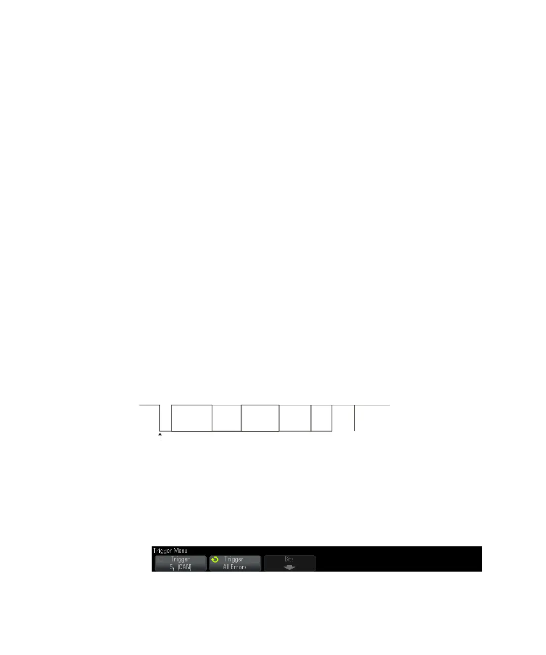
A CAN message frame in CAN_L signal type is shown below:
After setting up the oscilloscope to capture a CAN signal:
1 Press [Trigger].
2 In the Trigger Menu, press the Trigger softkey; then, turn the Entry knob to
select the serial slot (Serial 1) on which the CAN signal is being decoded.
Arbitration
Field
Bus
Idle
Data
Field
SOF edge
Control
Field
ACK
Field
Intermission
CRC
Field
EOF