Connecting the outputs
All loads should either be connected to the front panel binding post or rear panel output.
Binding posts
SHOCK HAZARD
Turn off AC power before connecting wires to the front panel. All wires and straps must be properly connected
with the binding posts securely tightened. For the E36234A model, ensure that proper wire insulation is used
(>120V) when enabling output voltage exceeding 60 VDC to avoid electric shock hazard.
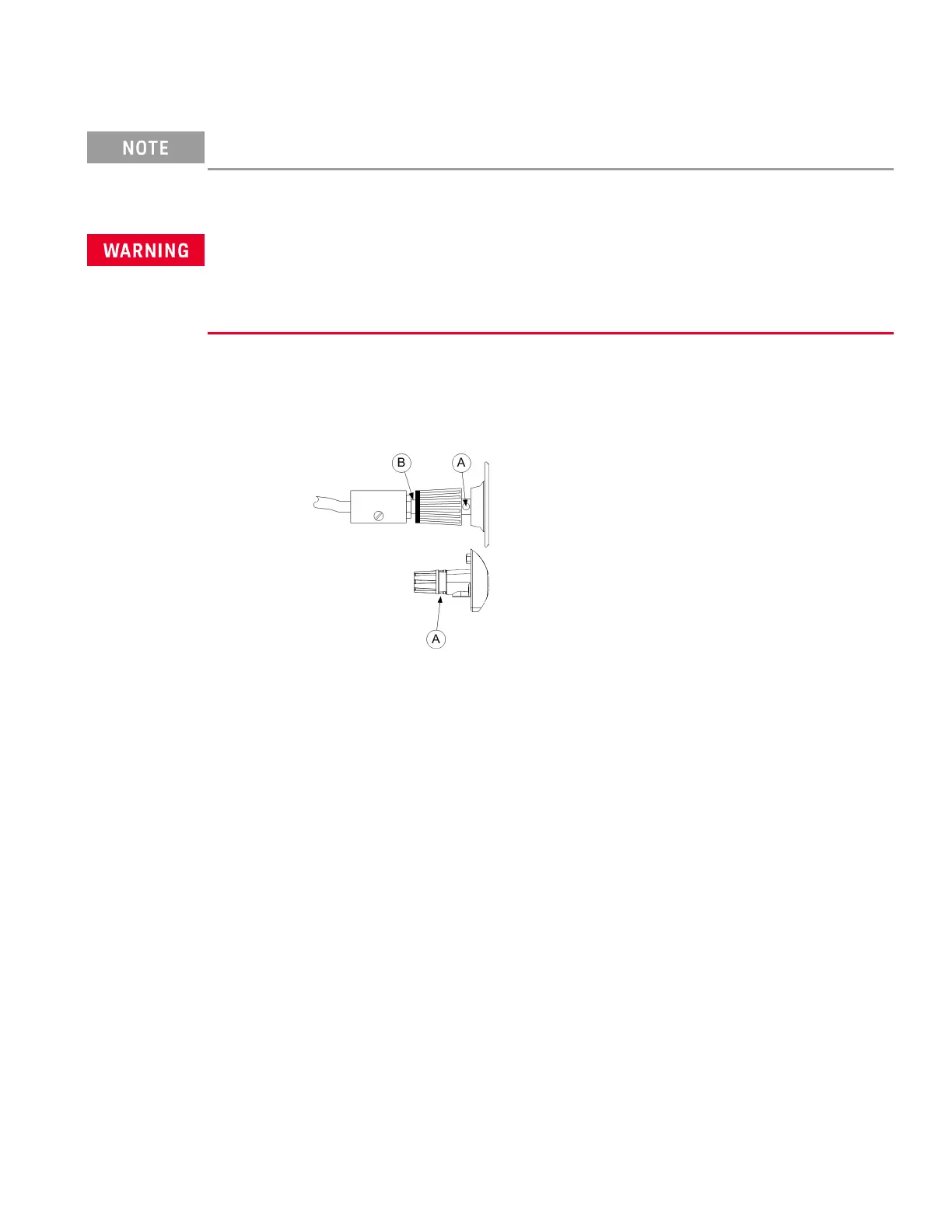
The binding posts accept wires sizes up to AWG 14 (AWG 12 for E36233A) in location (A). Securely fasten all wires by
hand-tightening the binding posts. You can also insert standard banana plugs into the front of the connectors as
shown in (B). A chassis ground binding post is located on the front panel for convenience.
Maximum current rating:
E36231A/E36232A/E36234A
(A) = 20 A
(B) = 15 A
E36233A
(A) = 40 A
Keysight E36200 Series User's Guide 31

 Loading...


