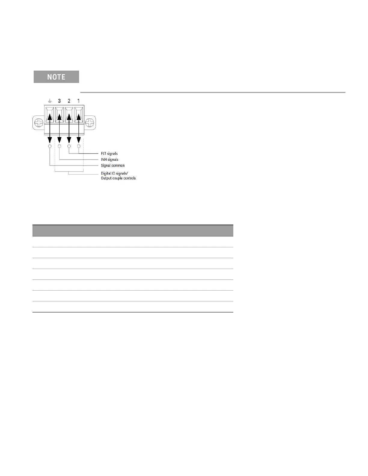
Digital port connections
A 4-pin connector is provided on each instrument to access the three digital control port functions. The digital
control connector accepts wire sizes from AWG 16 to AWG 22.
It is good engineering practice to twist and shield all signal wires to and from the digital connectors. If shiel-
ded wire is used, connect only one end of the shield to the chassis ground to prevent ground loops.
Pin functions
The following table describes the possible pin configuration for the digital port functions. For a complete description
of the electrical characteristics of the digital I/O port, refer to the product data sheet.
Pin function Available configurable pins
Digital I/O and Digital In Pins 1 through 3
External Trigger In/Out Pins 1 through 3
Fault Out Pin 1 and Pin 2
Relay Pin 1 and Pin 2
Inhibit In Pin 3
Output Coupling Pins 1 through 3
Common Pin 4
In addition to the configurable pin functions, the active signal polarity for each pin is also configurable. When
Positive polarity is selected, a logical true signal is a voltage high at the pin. When Negative polarity is selected, a
logical true signal is a voltage low at the pin.
For more information on configuring the digital port functions, refer to Using the Digital Control Port.
Keysight E36200 Series User's Guide 43

 Loading...


