August 2013 2-6 P/N 06-236530-001
2-4.1 Preparing the Enclosure for Wall Mounting
For either mounting configuration:
1. Remove the keys from the envelope taped to the top of the enclosure and open the
door to the control unit.
2. Disconnect the ground wire that connects the enclosure door to the back box.
3. Remove the control unit front door first by unlocking it and rotating the door
approximately 90° from its closed position.
4. Lift up the door to allow the door’s hinge pins to clear the mating-hinge sockets on
the back box.
5. Remove the separately packaged power supply, printed-circuit board, and plastic
bag (i.e., ship kit) containing installation hardware, and set them and the front door
aside in a safe location to prevent damage.
6. Locate the top of the cabinet approximately 66” above the floor so that the control
unit’s display is positioned at a convenient height for viewing system events and for
entering operator commands.
2-4.2 Surface Mounting
To surface mount the control unit:
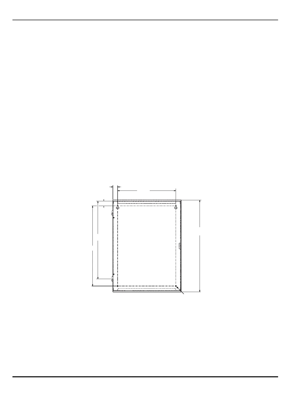
1. Mark and pre-drill holes for four mounting bolts using the dimensions shown in
Figure 2-2. The installer must supply the mounting bolts (up to size 1/4-20). There
are two holes and two keyhole slots in the enclosure’s rear panel that serve as a
template for surface mounting.
Figure 2-2. Back Box Mounting Dimensions
2. Insert the upper two fasteners in the wall. Leave approximately 1/4” protruding
for both screws.
3. Slip upper keyholes of the back box over the two protruding screws. Tighten the
screws.
4. Insert and tighten the two lower screws.
5. Attach wiring conduit to the enclosure via the enclosure knockouts, and pull the
required number of wires through the conduit to the enclosure. Leave
19.456
0.281 Diameter
Holes Typ (2) Places
17.000
16.500
1.000
1.000
12.250