P/N 06-236530-001 2-21 August 2013
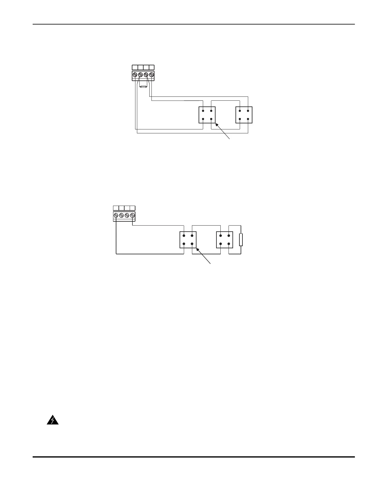
Figure 2-20 shows typical wiring for a combination circuit wired as a Class-A, Style-Z
notification appliance circuit.
Figure 2-20. Combination Circuit used as Class-A, Style-Z NAC
Figure 2-21 shows typical wiring for a combination circuit wired as a Class-B, Style-Y
notification appliance circuit.
Figure 2-21. Combination Circuit used as Class-B, Style-Y NAC
Use Figure 2-19 to estimate the maximum length of wire as a function of notification-
appliance current for a combination circuit used as a NAC.
2-10.2 Combination Circuits used as Releasing Circuits
Each combination circuit can be configured as a releasing circuit to activate either one
Kidde control head or one pre-action-sprinkler or deluge-sprinkler valve. Total current
output of the ARIES power supply must not exceed 5.4 A.
Both combination circuits are supervised and power limited when configured as releasing
circuits and when the in-line device, P/N 06-220023-001, is wired in series with the
solenoid valve. The compatible control heads and solenoid valves are listed in
Appendix C. Refer to the ARIES Programmer’s Guide to configure one or both
combination circuits as releasing circuits.
Route non-power limited wiring at least 1/4 inch away from all power-limited wiring.
WARNING
Ensure that all releasing devices are physically disconnected from the releasing
circuits before performing any system testing or maintenance.
-
+
-
+
Polarized Notification Appliance
(Typical)
Supervised and Power-Limited
4321
Combo 1 or
Combo 2
End-of-Line Resistor
10k +/- 10%, 0.5W
TB7 or
TB6
-
+
-
+
4321
End-of-Line Resistor
10 k +/- 10%, 0.5 W
Combo 1 or
Combo 2
Polarized Notification Appliance
(Typical)
Supervised and Power-Limited
TB7 or
TB6