P/N 06-236530-001 3-131 August 2013
3-3.15 Remote Alarm Events
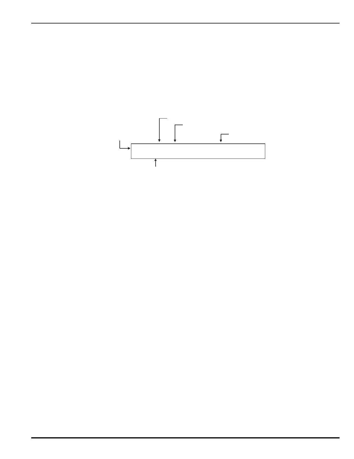
Remote alarm events from a networked control unit are shown in the upper line of the
LCD display by:
•Node-of-origin
• Device address
•Change of state
•Device type
The lower line indicates the up-to-40-character message assigned to the alarm-initiating
device using the ARIES configuration program.
Figure 3-62. Typical Remote Alarm Message Display
The following actions also occur when the control unit is configured as Group 0 or when
the alarm event is either from another control unit in the same group as the control unit
or from any other control unit in a network configured for global operation.
1. The Alarm LED on the display flashes
2. The internal buzzer sounds continuously
3. The alarm event is stored in the event log
4. The alarm message is transmitted to peripheral devices such as RDCMs and ATM-
Ls, if applicable
5. The alarm message is communicated via the NIC and RS-232 ports, as applicable
6. Point- or group-specific and general-alarm outputs activate, including previously-
silenced outputs.
Refer to Paragraph 3-2.5.4.1 for what to do when a remote alarm message is received.
3-3.16 Remote Positive-Alarm-Sequence (PAS) Events
Remote PAS events from a networked control unit are shown in the upper line of the LCD
display by:
•Node-of-origin
• Device address
•Change of state
•Device type
The lower line indicates the up-to-40-character message assigned to the alarm-initiating
device using the ARIES configuration program.
N:02 010 ALARM ON MANUAL STATION
COMPUTER ROOM
Node Number
Device Address 010
Alarm Indication
Device Type
Reporting Alarm
Device-Specific
Custom Message