August 2013 2-28 P/N 06-236530-001
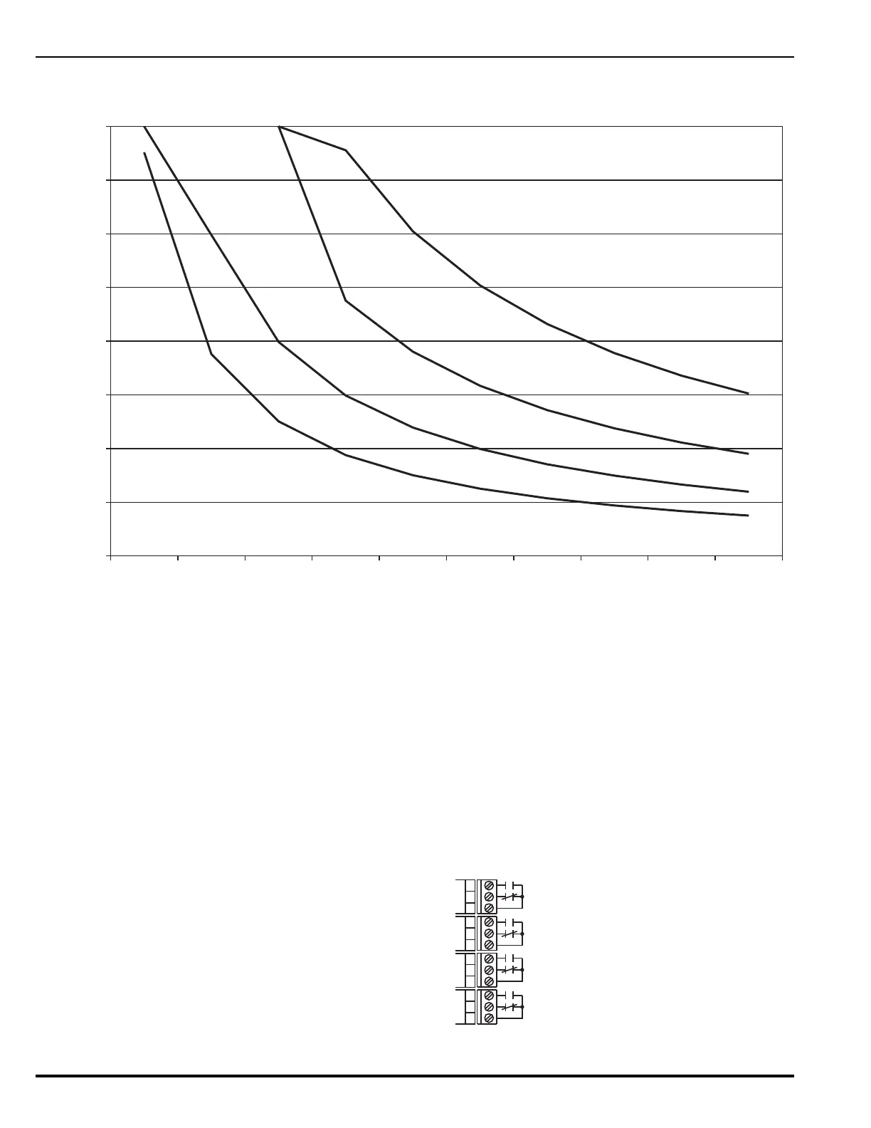
Use Figure 2-29 to estimate the maximum length of wire that can be connected to an Auxiliary-
Power Output as a function of RS-485 peripheral-devices current.
Figure 2-29. 24 Vdc-Power Wiring Length vs. Peripheral-Devices Current
Refer to the installation manuals for the remote display module and driver modules for address
selection and additional point-to-point-connection details. The numbers of peripheral devices for
a particular application are specified via the ARIES Programmer’s Guide.
2-14 RELAYS
The ARIES Control Unit has three Form-C, programmable relays and one Form-C, trouble relay
as shown in Figure 2-30. All of these relays have the following contact ratings:
• 1.0 A @ 30 Vdc (resistive)
• 0.5 A @ 30 Vdc (inductive)
• 0.5 A @ 120 Vac (inductive)
Figure 2-30. Programmable and Trouble Relays
0
500
1000
1500
2000
2500
3000
3500
4000
0.1 0.2 0.3 0.4 0.5 0.6 0.7 0.8 0.9 1.0
Total Current (A) for RS-485 Peripheral Devices
0.0
#18 AWG
#16 AWG
#14 AWG
#12 AWG
Maximum Distance (Ft.)
NCNO
C
NCNO
C
NCNO
C
NCNO
C
Programmable Relay No. 1
Programmable Relay No. 2
Programmable Relay No. 3
Relay No. 4 (Trouble)