August 2013 2-22 P/N 06-236530-001
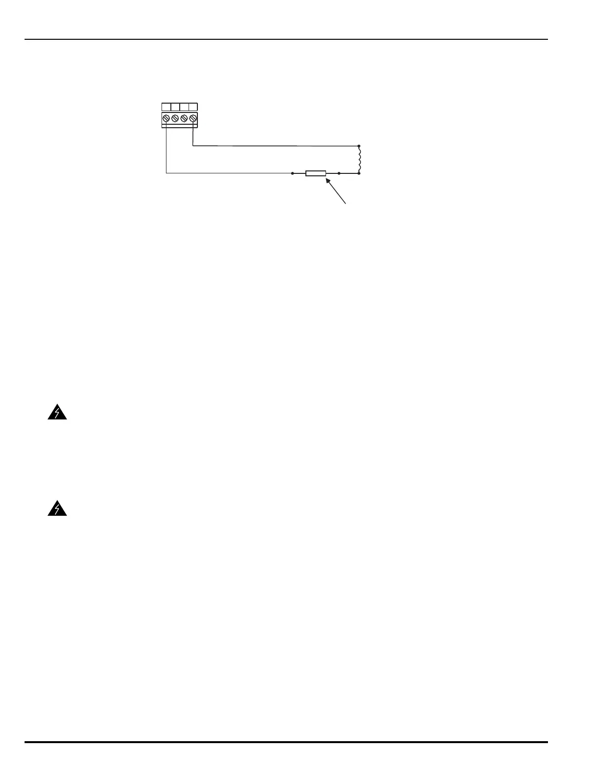
Figure 2-22 shows a combination circuit wired for releasing. Refer to Appendix C for
further information.
Figure 2-22. Combination Circuit used as Releasing Circuit
2-11 RELEASING CIRCUITS
The ARIES has two releasing circuits that can be configured to actuate extinguishing systems
through any of the following ways:
• Single actuator assembly
• Single control head or solenoid valve
• Two series-supervised, parallel-actuated control heads or solenoid valves.
The release circuits are labeled Release1 and Release2 and have field-wiring connections that
terminate at TB12 and TB11, respectively.
2-11.1 Releasing Circuits for Actuator Assembly
Figure 2-23 shows an actuator assembly connected to a releasing circuit. Each releasing
circuit is capable of actuating one actuator assembly.
WARNING
Ensure that all releasing devices are physically disconnected from the releasing
circuits before performing any system testing or maintenance.
WARNING
Actuator assembly is a non-explosive device. Do not remove the shorting cap
from the cable connector until the field-wiring connections are to be made.
Physical abuse or static-electricity discharge could cause inadvertent actuator
actuation. The installer must establish a common electrical potential with the
actuator assembly before either removing or inserting the shorting cap.
4321
Combo 1 or
Combo 2
In-Line Releasing Device (P/N 06-220023-001)
(Must be close nippled to solenoid enclosure)
Supervised and Power-Limited
BlkRed
Solenoid
(Refer to Appendix C)
TB7 or
TB6