August 2013 2-16 P/N 06-236530-001
2-8.1.2 CLASS-A, STYLE-6 WIRING REQUIREMENTS
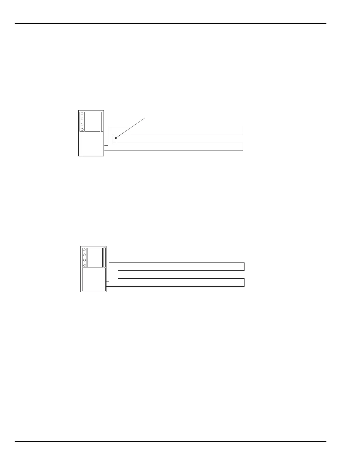
Note: The following resistance reading MUST be taken PRIOR to the installation
of any peripheral device.
The total wiring resistance from the start of the “Out” leg to the end of the
“Return” leg cannot exceed 40 ohms. Use the following procedure to determine
the wiring resistance.
1. Short the “Out” and “Return” legs as shown in Figure 2-13. Measure the
resistance using the other two terminating points at the control unit
2. Remove the shorting jumper after the resistance measurement.
Figure 2-13. Measuring Class-A SLC Wiring Resistance
The total wiring capacitance cannot exceed 0.5 F. Use the following procedure to
determine the wiring capacitance.
Note: The following capacitance reading MUST be taken PRIOR to the installation
of any peripheral device.
1. Measure the capacitance using the wiring that will connect to control unit
terminals TB1-1 and TB1-3 (Terminals TB1-2 and TB1-4 MUST remain
disconnected from the control unit) as shown in Figure 2-14.
Figure 2-14. Measuring Class-A SLC Wiring Capacitance
Figure 2-15 shows typical wiring for a Class-A, Style-6 signaling line circuit. Make
sure that the SLC-Selector Switch S2 is moved to the right into the Style-6
position. Refer to Figure 1-3
Note: Isolator modules are not required for a Class-A, Style-6 signaling line
circuit. A maximum of 30 SmartOne devices can be installed between a
pair of isolator modules.
Jumper
Out Leg
Return Leg
Volt-Ohm Meter
Out Leg
Return Leg
Capacitance Meter