P/N 06-236530-001 2-15 August 2013
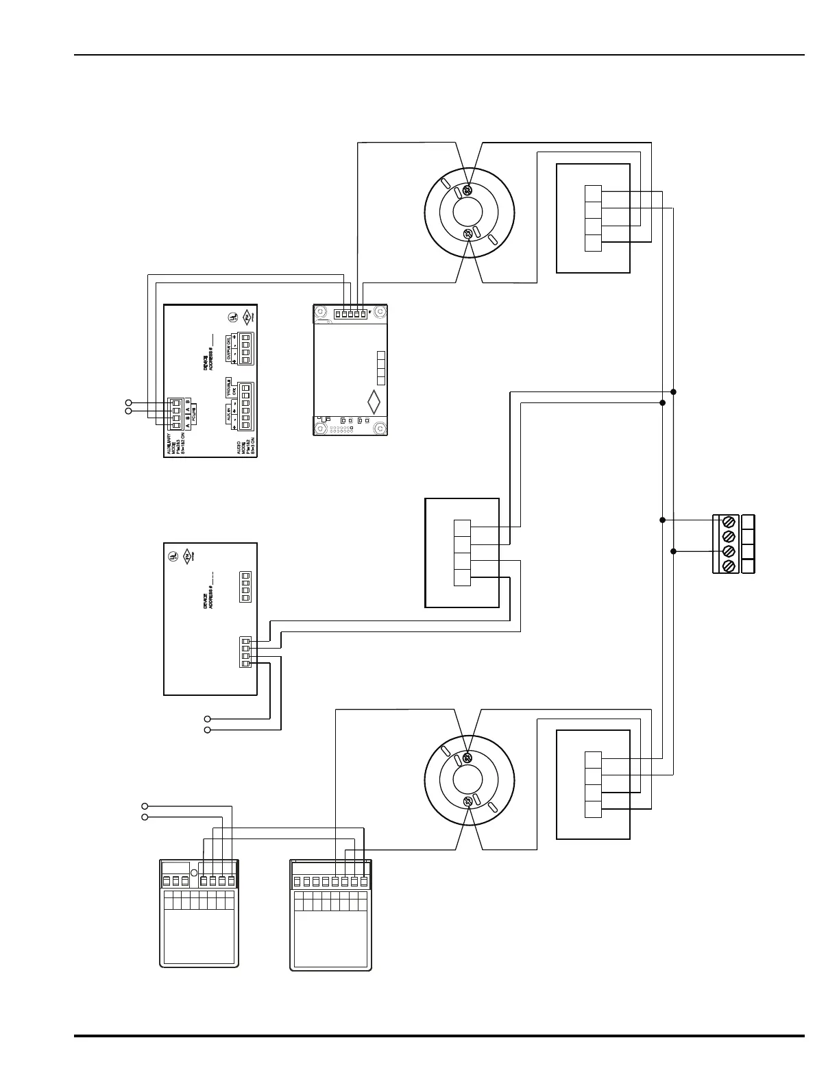
Note: Isolator modules are not required for a Class-B, Style-4 signaling line
circuit. A maximum of 30 SmartOne devices can be installed between
a pair of isolator modules.
Figure 2-12. Class-B, Style-4 Signaling Line Circuit
RET RET24 V 24 V
OUT IN
RET RET24 V 24 V
OUT IN
4321
3
7
3
7
765
4321
PC PC PC PC
(+) (-) (+) (-)
N/C
COM
N/O
7654321
PC PC PC PC
(+) (-) (+) (-)
8
A
SW
B
SW
(+)
LED
(-)
LED
AO Relay Module
AI Monitor Module
Detector Base
Isolator Module
(Single-Gang Mount)
Isolator Module
(Single-Gang Mount)
AAM AlarmLine Module
Isolator Module
(Single-Gang Mount)
Detector Base
PALM Monitor Module
BABA
INOUT
PC LINE
BLU
RED
WHT
ORN
ASM Signal Module
To Next Device To Next Device
To Next Device
ADDRESS
FM
APPROVED
IN
OUT
RXTX
RXTX
GND
Branch 1
Branch 2
Branch N
SLC Terminals on
Printed-Circuit Board
(TB1)
Notes:
1. Move SLC-Style Switch S2 to the left into the Style-4 position.
2. Each isolator module creates a 0.12-V voltage drop.
RET RET24 V 24 V
OUT IN
Caution:
Do not use looped wire under terminals of
detector bases. Break SLC wire run to provide
supervision of connections
.