August 2013 2-14 P/N 06-236530-001
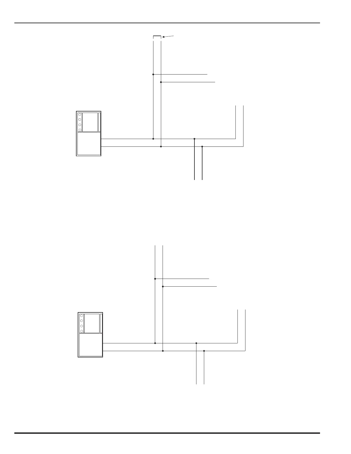
Figure 2-10. Measuring Class-B SLC Wiring Resistance
The total wiring capacitance cannot exceed 0.5 F. Use the following procedure to
determine the wiring capacitance.
1. Ensure that the ends of each branch line are open circuited.
2. Measure the capacitance from the terminating points at the control unit
using a capacitance meter. See Figure 2-11.
Figure 2-11. Measuring Class-B SLC Wiring Capacitance
Figure 2-12 shows typical wiring for a Class-B, Style-4 signaling line circuit. Make
sure that the SLC-Selector Switch S2 is moved to the left into the Style-4 position.
Refer to Figure 1-3.
Jumper
Branch 1
Branch 2
Branch 3
Branch N
Volt-Ohm Meter
Branch 1
Branch 2
Branch 3
Branch N
Capacitance Meter