P/N 06-236530-001 2-39 August 2013
2-19 INTELLIGENT INTERFACE MODULE
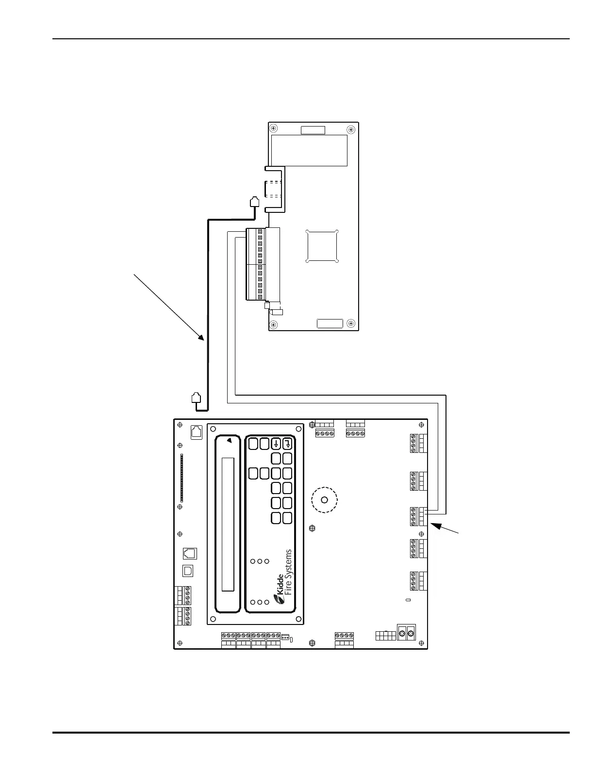
The interconnection of the Intelligent Interface Module to the ARIES Control Unit is shown in
Figure 2-40. Refer to the ORION-XT Installation, Operation and Maintenance Manual
(Publication 77.100) for additional details.
Figure 2-40. Interconnection of IIM
Combo 2
TB6TB7
Combo 1
TB2
Aux 24 VDC
TB11
Release 2
TB12
Release 1
Batt Out
TB3
TroubleRelay 3Relay 1 Relay 2
1234 1234
1234
1234 1234
120
240
TB13
AC IN
NL
PSU
J12
+
+
--
CNCNO
CNCNO
CNCNOCNCNO
1234
TB5
NAC 1
TB14
1234
NAC 2
RS-232 A
J8
J5
TB15
USB B
RS 485SLC
TB1
4321
4321
Style 4
S2
J10
J3
RS-232 B
TB4 TB8 TB9 TB10
CCM PC TEL
123456
7
89101112
RS-232 Communications Cable
Connect from IIM Port labeled "CCM"
to control-unit port J8 (RS-232 A).
Configure Port J8 for operation with IIM.
Refer to Paragraph 3-2.5.2.4.5
Control-Unit PCB
IIM PCB
AC POWER
ALARM
PRE-ALARM
SYSTEM TROUBLE
SUPERVISORY
SILENCE
SYSTEM
ACKNOWLEDGE
SYSTEM
RESET
SILENCE
SCROLL
1 2 3 4 5
6 7 8 9 0
Auxiliary Power Terminals
(Non re-settable)