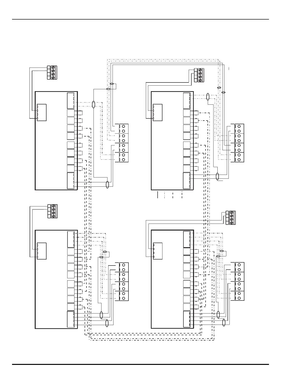
Figure 2-39. Typical Dual-Channel System using Combination Twisted, Shielded and Fiber Optic Media
Node 1
Node 2
Node N
Node 3
B2 N A2
B1 N A1 B2 I A2 B1 I A1
TB1TB3TB2TB4
TB1
RxN TxN RxI
Q1 D1 Q2 D3
TxI RxN TxN RxI TxI
Q3 D5 Q4 D7
B1N B1IA1N A1I
TB2
B2N B2IA2N A2I
24V
+ -+ -
B2 N A2
B1 N A1 B2 I A2 B1 I A1
TB1TB3TB2TB4
TB1
RxN TxN RxI
Q1 D1 Q2 D3
TxI RxN TxN RxI TxI
Q3 D5 Q4 D7
B1N B1IA1N A1I
TB2
B2N B2IA2N A2I
24V
+ -+ -
B2 N A2
B1 N A1 B2 I A2 B1 I A1
TB1TB3TB2TB4
TB1
RxN TxN RxI
Q1 D1 Q2 D3
TxI RxN TxN RxI TxI
Q3 D5 Q4 D7
B1N B1IA1N A1I
TB2
B2N B2IA2N A2I
24V
+ -+ -
B2 N A2
B1 N A1 B2 I A2 B1 I A1
TB1TB3TB2TB4
TB1
RxN TxN RxI
Q1 D1 Q2 D3
TxI RxN TxN RxI TxI
Q3 D5 Q4 D7
B1N B1IA1N A1I
TB2
B2N B2IA2N A2I
24V
+ -+ -
Channel 1
Channel 2
Channel 1 Channel 2
Channel 1
Channel 2
Channel 1
Channel 2
4321
TB2
Aux. Power Terminals
Control Unit PCB
(Non-Resettable)
4321
TB2
Aux. Power Terminals
Control Unit PCB
(Non-Resettable)
4321
TB2
Aux. Power Terminals
Control Unit PCB
(Non-Resettable)
4321
TB2
Aux. Power Terminals
Control Unit PCB
(Non-Resettable)
NIC Terminals
(Node 1)
NIC Terminals
(Node 2)
NIC Terminals
(Node 3)
NIC Terminals
(Node N)
OCC
(Node 1)
OCC
(Node 2)
OCC
(Node 3)
OCC
(Node N)
Connect wires for shields
to ground screw in upper-
left-hand corner of NIC
Installation Notes:
1. Do not T-Tap the network fiber. Use daisy-chained interconnections.
2. Daisy chain fiber back from Node N to Node 1.
3. Use twisted, shielded wire for NIC - OCC and NIC - NIC interconnections.
Connect wires for shields
to ground screw in upper-
left-hand corner of NIC
Connect wires for shields
to ground screw in upper-
left-hand corner of NIC.
Max. 1 Mile of Fiber (62.5/125 um duplex)
between Control Units
Leave shield wire floating at Node 3. Do not connect wire for
shield to the earth-ground screw in upper-left-hand
corner of last NIC. Trim shield wire as much as possible.
Key
Ch1 Twisted,
Shielded Wire Pair
Ch2 Twisted,
Shielded Wire Pair
Ch1 62.5/125um
Duplex Fiber Optics
(ST Connectors)
Ch2 62.5/125um
Duplex Fiber Optics
(ST Connectors)
Connect wires for shields to ground screw
in upper-left-hand corner of NIC.
Note: All wiring is power-limited and supervised.