August 2013 2-18 P/N 06-236530-001
2-8.1.3 SPECIAL CLASS-A, STYLE-7 REQUIREMENTS
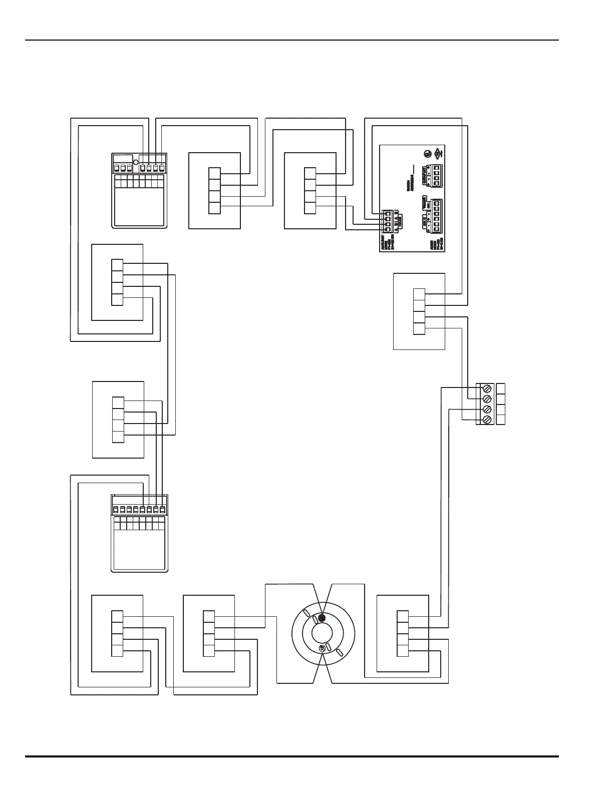
A Class-A, Style-7 signaling line circuit requires a pair of isolator modules for each
SmartOne device as shown in Figure 2-16. Make sure that the SLC-Selector
Switch S2 is moved to the right into the Style-6 position. Refer to Figure 1-3.
Figure 2-16. Class-A, Style-7 Signaling Line Circuit
RET RET24 V 24 V
OUT IN
RET RET24 V 24 V
OUT IN
4321
765
4321
PC PC PC P C
(+) (-) (+) (-)
N/C
COM
N/O
7654321
PC PC PC PC
(+) (-) (+) (-)
8
A
SW
B
SW
(+)
LED
(-)
LED
AO Relay Module
AI Monitor Module
Single-Gang-Mount
Isolator Module
(Typical)
See Note 2
ASM Signal Module
SLC Terminals on
Printed-Circuit Board
(TB1)
RET RET24 V 24 V
OUT IN
Notes:
1. All wiring shall be installed in conduit.
2. Install isolator modules as close as possible to protected devices (max. 20 feet).
3. Move the SLC-Style Switch S2 to the right into the Style-6 position.
4. Each isolator module creates a 0.12-V voltage drop.
RET RET24 V 24 V
OUT IN
RET RET24 V 24 V
OUT IN
3
7
Detector Base
Caution:
Do not use looped wire under terminals of
detector bases. Break SLC wire run to provide
supervision of connections
.
RET RET24 V 24 V
OUT IN
RET RET24 V 24 V
OUT IN
RET RET24 V 24 V
OUT IN