P/N 06-236530-001 1-3 August 2013
A switching power supply is located behind the printed-circuit board and supplies 5.4 A
@ 24 Vdc to support the basic control unit and its associated peripheral devices and to
charge the standby battery. The switching power supply is user-configurable to operate
from either 120 or 240 Vac, 50/60 Hz primary power.
1-2 CONTROL UNIT COMPONENTS
The ARIES System includes:
•Display
• Printed Circuit Board (PCB)
•Cabinet
• Power Supply/Battery Charger Assembly
Optional devices includes:
• Remote Display/Control Module (RDCM)
• ATM Series Driver Module (ATM-L/-R)
• Intelligent Interface Module (IIM)
• Network Interface Card (NIC)
• Fiber-Optic Converter Card (OCC)
•Trim Ring
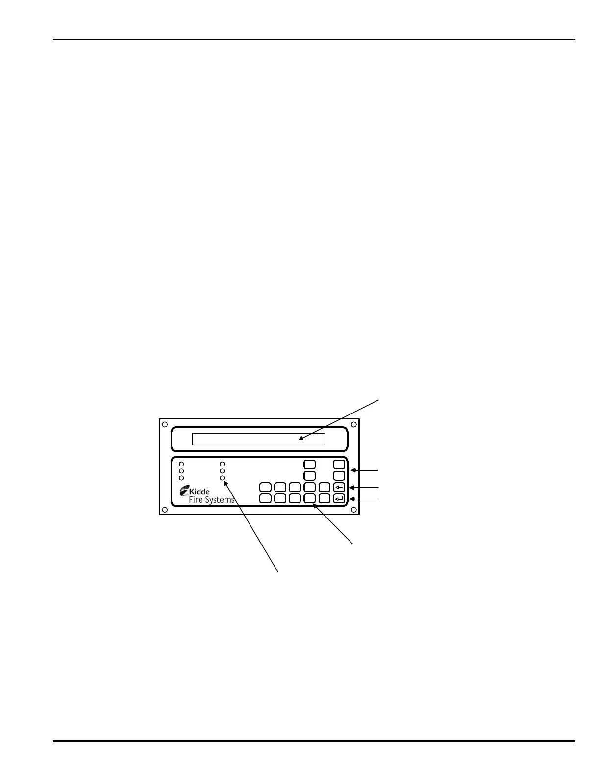
1-2.1 Display
The display (Figure 1-2) has control switches, system status LEDs, an 80 character (2 x
40) LCD for event annunciation and an integral numeric keypad. The keypad is used for
entering the security password and navigating through the user menus.
Figure 1-2. ARIES Display
The following paragraphs describe the different parts of the display.
1-2.1.1 LCD AND LEDS
A window for the 80-character (two lines by 40 characters each) LCD and six
system-status LEDs. The six system-status LEDs are:
• Power On (green)
•Alarm (red)
• Pre-Alarm (yellow)
AC POWER
ALARM
PRE-ALARM
SYSTEM TROUBLE
SUPERVISORY
SILENCE
SYSTEM
ACKNOWLEDGE
SYSTEM
RESET
SILENCE
SCROLL
1 2 345
6 7 890
80 Character
Liquid Crystal Display
with LED Back Lighting
(2 Lines X 40 Characters)
12-key numeric / BACKSPACE /
ENTER keypad
ENTER Key
BACKSPACE Key
Operator Control Keys
System Status LEDs