P/N 06-236530-001 2-31 August 2013
2-17.1 How to Install a NIC
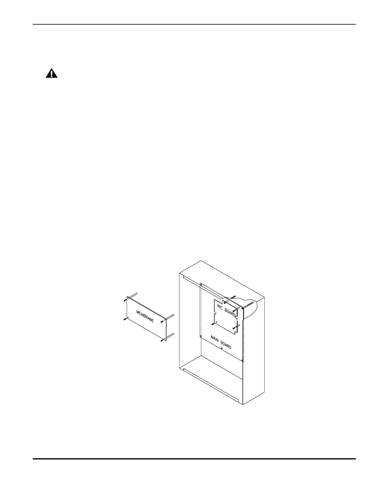
Refer to Figure 2-33 before you install the NIC and perform the following procedure to
install the NIC on the ARIES’s printed-circuit board.
1. Slip on a wrist ground strap and connect the clip to the earth ground in the
enclosure. Do not remove the NIC from its shipping carton unless you have
established a common earth-ground potential among yourself, the enclosure, and
the NIC’s shipping carton.
2. Remove the four screws holding the keypad / display to the main PCB. Carefully pull
out the keypad/display from its connectors to the PCB and set aside in a clean, dry
location.
3. Remove the NIC from its shipping carton and locate the three plastic standoffs
included in the installation kit. Insert these standoffs into the three mounting holes
in the PCB as shown in Figure 2-33.
4. Carefully insert the NIC into the 20-pin connector J5 and attach it to the three
plastic standoffs.
5. Secure the upper left-hand corner of the NIC with the long screw and spacer
supplied with the installation kit. The spacer will separate the NIC and the PCB and
the screw will connect to the chassis. Do not over-tighten the screw.
6. Carefully plug the display into its receptacles on the PCB and re-attached with the
four screws. Be sure that the display pins and the PCB receptacles are properly
aligned.
7. Connect network wiring as shown in Paragraph 2-17.2.
Figure 2-33. NIC Installation
2-17.2 Network Wiring
Typical Class-B, Style-4 and Class-A, Style-7 wiring are shown in Figure 2-34 and
Figure 2-35, respectively.
CAUTION
Remove AC and DC power from the control unit before you install a NIC.