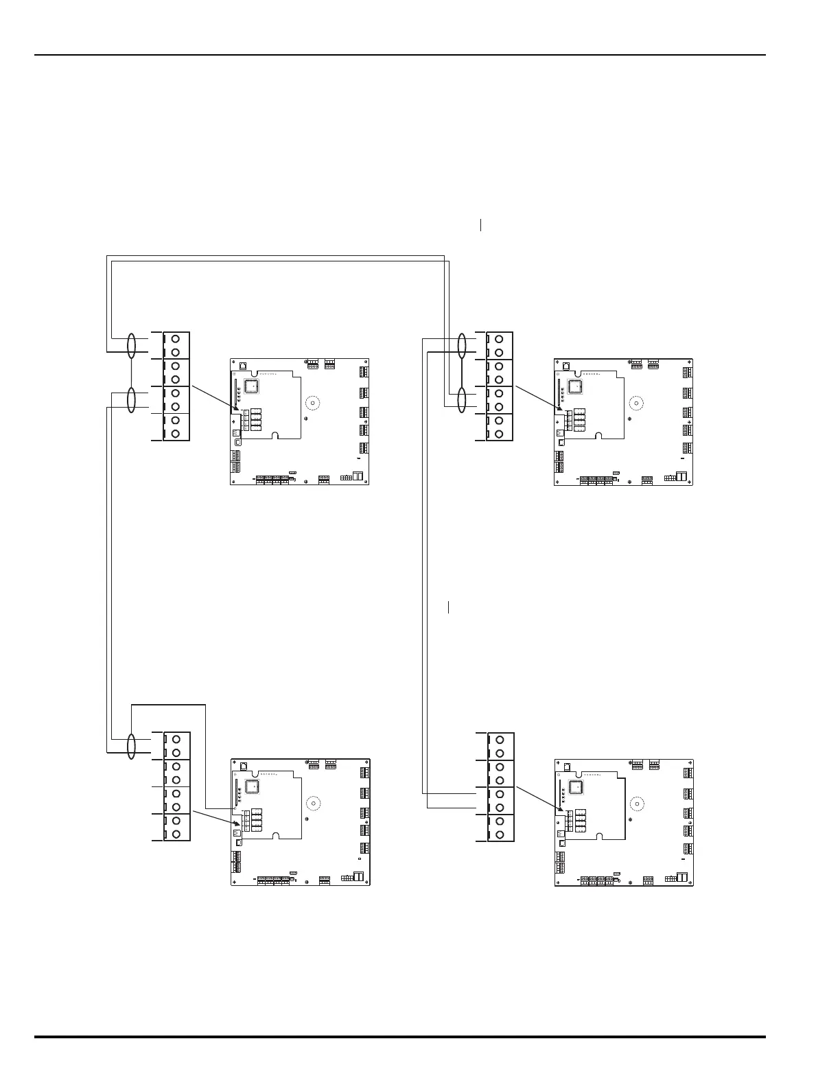
back from Node N to Node 1.
Figure 2-34. Class-B, Style-4 Network Wiring
Combo 2
TB6TB7
Combo 1
TB2
Aux 24 VDC
TB11
Release 2
TB12
Release 1
Batt Out
TB3
TroubleRe la y 3
Rela y 1
Rela y 2
1234 1234 1234 1234 1234
120
240
TB13
AC In
NL
PSU
J12
+
+
--
CNCNO
CNCNO
CNCNOCNCNO
SLC
1234
TB5
NAC 1
TB4
1234
NAC 2
RS-232
J8
J8
TB15
USB B
RS 485SLC
TB1
4321
4321
Style 4
S2
J10 J11
B2NA2 B1NA1 B2IA2 B1IA1
TB1TB3TB2TB4
K1K3K2K4
J1
DS4 DS2 DS3 DS1
N2 N1 I2 I1
U11
GND
TP1
+5
TP2
I1
TP3
N1
TP4
N2
TP5
I2
TP6
B2 N A2
B1 N A1 B2 I A2 B1 I A1
TB1TB3TB2TB4
Combo 2
TB6TB7
Combo 1
TB2
Aux24VDC
TB11
Release 2
TB12
Release 1
Batt Out
TB3
TroubleRe la y 3
Rela y 1
Rela y 2
1234 1234 1234 1234 1234
120
240
TB13
AC In
NL
PSU
J12
+
+
--
CNCNO
CNCNO
CNCNOCNCNO
SLC
1234
TB5
NAC 1
TB4
1234
NAC 2
RS-232
J8
J8
TB15
USB B
RS 485SLC
TB1
4321
4321
Style 4
S2
J10 J11
B2NA2 B1NA1 B2IA2 B1IA1
TB1TB3TB2TB4
K1K3K2K4
J1
DS4 DS2 DS3 DS1
N2 N1 I2 I1
U11
GND
TP1
+5
TP2
I1
TP3
N1
TP4
N2
TP5
I2
TP6
B2 N A2
B1 N A1 B2 I A2 B1 I A1
TB1TB3TB2TB4
Maximum 4,000 Ft of Wire (#18 AWG or larger) between Control Units
(Twisted, Shielded, Low-Capacitance Wire)
Node 1
Node 2
Node N Node 3
Notes:
1. Do not T-Tap the network wiring. Use
diasy-chained wiring style only.
2. Do not daisy chain wiring back from
Node N to Node 1.
Connect wire for shield to earth-ground screw
in upper-left-hand corner of NIC.
Connect wires for shields together at each
intermediate NIC. Do not connect wires for
shields to the earth-ground screw in
upper-left-hand corner of intermdiate NICs.
Leave shield wire floating at last NIC. Do not connect wire for
shield to the earth-ground screw in upper-left-hand
corner of last NIC. Trim shield wire as much as possible.
Note: All wiring is power-limited and supervised.