VOLTAGE Cursors button (16) - Generates two linear cursor bars which
provide accurate differential voltage measurements when adjusted
vertically on the currently displayed waveform. The REFERENCE and
DIFFERENCE controls (38) serve to position the Reference and the
Difference cursor bars.
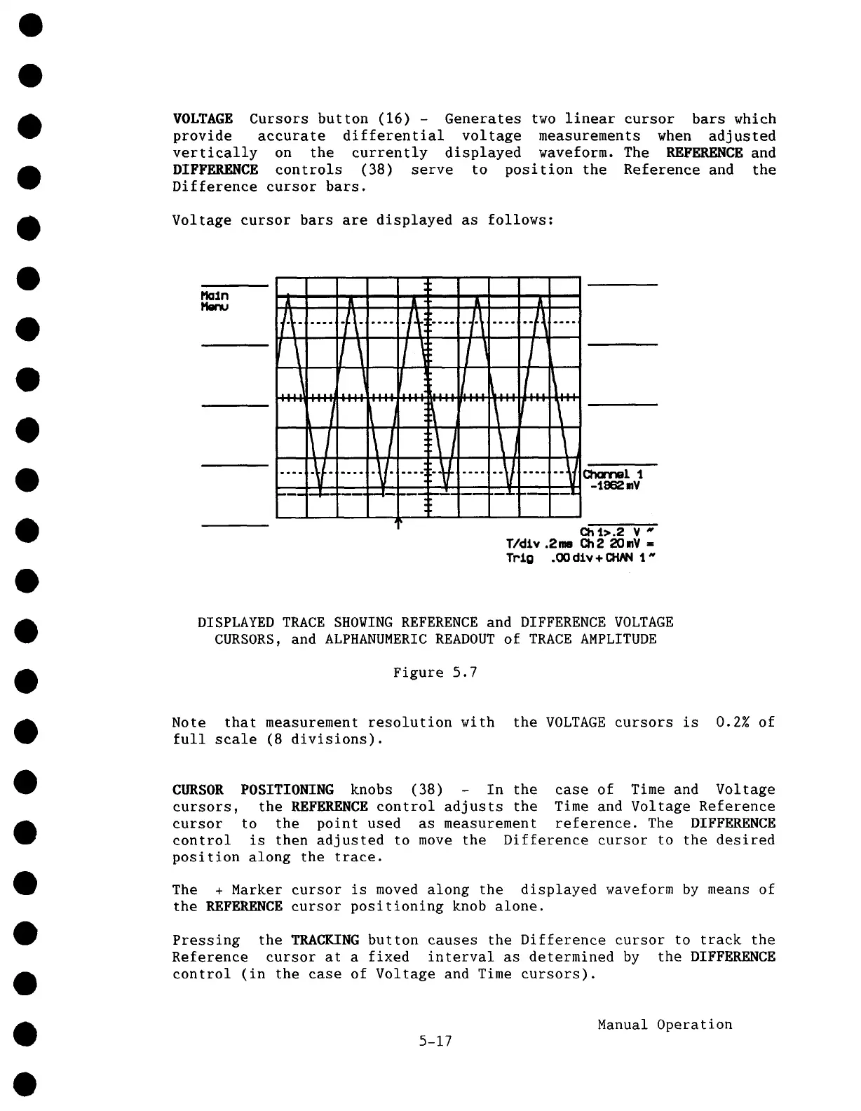
Voltage cursor bars are displayed as follows:
R
A .....A ........
.... ~ .......
V-
A A A
-I~ -I-I ......-I~ ......
II I~ I
.... , ....I...~... I... ~...
....
1’ .... / ....... \
~ll \J
.... i::--V- --V
~
......
V
¯
.I. I-
Q14.>.2 V "
T/oiLy .2me Ch2 2C)mV
Tr’J.o .CX) dlv÷ CHNq 1
DISPLAYED TRACE SHOWING REFERENCE and DIFFERENCE VOLTAGE
CURSORS, and ALPHANUMERIC READOUT of TRACE AMPLITUDE
Figure 5.7
Note that measurement resolution with the VOLTAGE cursors is 0.2% of
full scale (8 divisions).
CURSOR POSITIONING knobs (38) - In the
case of Time and Voltage
cursors, the REFEP~NCE control adjusts the
Time and Voltage Reference
cursor to the point used as measurement reference. The DIFFERENCE
control is then adjusted to move the Difference cursor to the desired
position
along the trace.
The + Marker cursor is moved along the displayed waveform by means of
the REFERENCE cursor positioning knob alone.
Pressing the TRACKING button causes the Difference cursor to track the
Reference cursor at a fixed interval as determined by the DIFFERENCE
control (in the case of Voltage and Time cursors).
5-17
Manual Operation