Coupling Installation
Use the following steps for proper coupling installation:
1. Determine the correct torque value for your
coupling.
NOTE: Only use the torque values specied from
the manufacturer. DO NOT use SAE torque
recommendations.
2. Ensure the seal face and threads are clean and in
good condition. O-Rings should be lubricated with
light oil, but threads should be completely dry unless
making pipe thread connections (interference seal).
NOTE: Attach the male end of the hose onto the
equipment rst since it may be necessary to
rotate the entire hose assembly to tighten the
male threads. Then route the hose into position
while avoiding twisting the hose.
3. Tighten the connection (by hand), bringing the seal
face into contact and rotating the nut until it stops.
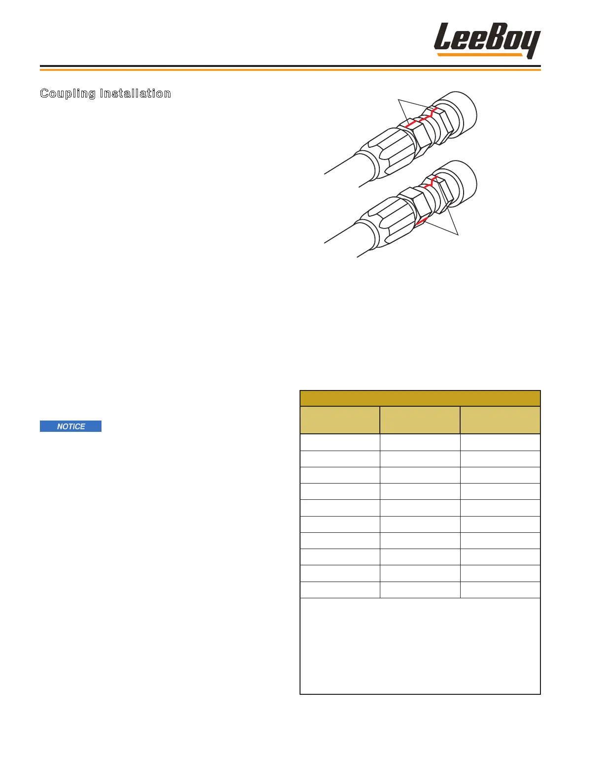
4. Mark a line across the coupling nut and backup hex
for the ats method verication of coupling torque
(Figure 2-512).
5. Apply a wrench to the backup hex to prevent the
coupling and hose from moving while tightening the
nut with a torque wrench.
Failure to retain the backup hex during
installation will also result in additional clamp load
force that could cause damage to the seal face.
NOTE: The coupling nut must be in motion for an
accurate torque reading. If the nut is stopped
before nal torque value is achieved, it must be
loosened and retightened until the torque is
attained while the nut is in motion.
If a torque wrench cannot t into the coupling area or if
it is unavailable, the ats method may be used to ensure
that the coupling is properly tightened, as shown in
Figure 2-55:
Example 2 Flats
difference
Figure 4-6. Flats Method Tightening
NOTE: The mark placed on the nut and backup hex
after tightening by hand should rotate during nal
tightening according to the table below. (Figure
2-12) The nut and backup hex can then be
marked to indicate if the coupling loosens over
time.
Table 1-6. Flats Method Values for Selected
Terminations
FLATS METHOD VALUES
Termination
Type
Dash Size Flats
JIC -4 1.5 - 1.75
JIC -6 1.0 - 1.5
JIC -8 1.5 - 1.75
JIC -10 1.0 - 1.5
JIC -12 1.0 - 1.5
JIC -16 .75 - 1.0
JIC -20 .75 - 1.0
JIC -24 .75 - 1.0
JIC -32 .75 - 1.0
JIS -4 .5 - 1.5
1. Seal faces must be in contact with the tting fully
tightened by hand before marking ats.
2. The ats method is most accurate for the rst
assembly cycle. For multiple disassembly and
assembly cycles, torque values are more reliable.
3. Tightening two (2) ats or more may damage seal
faces.
Information and Specications
3000C Force Feed Loader
2-10