132
T2
T4
T1
T3
T2
T4
T1
T3
H4651M2
L4651M2
AM581M2
573987
067242
067553
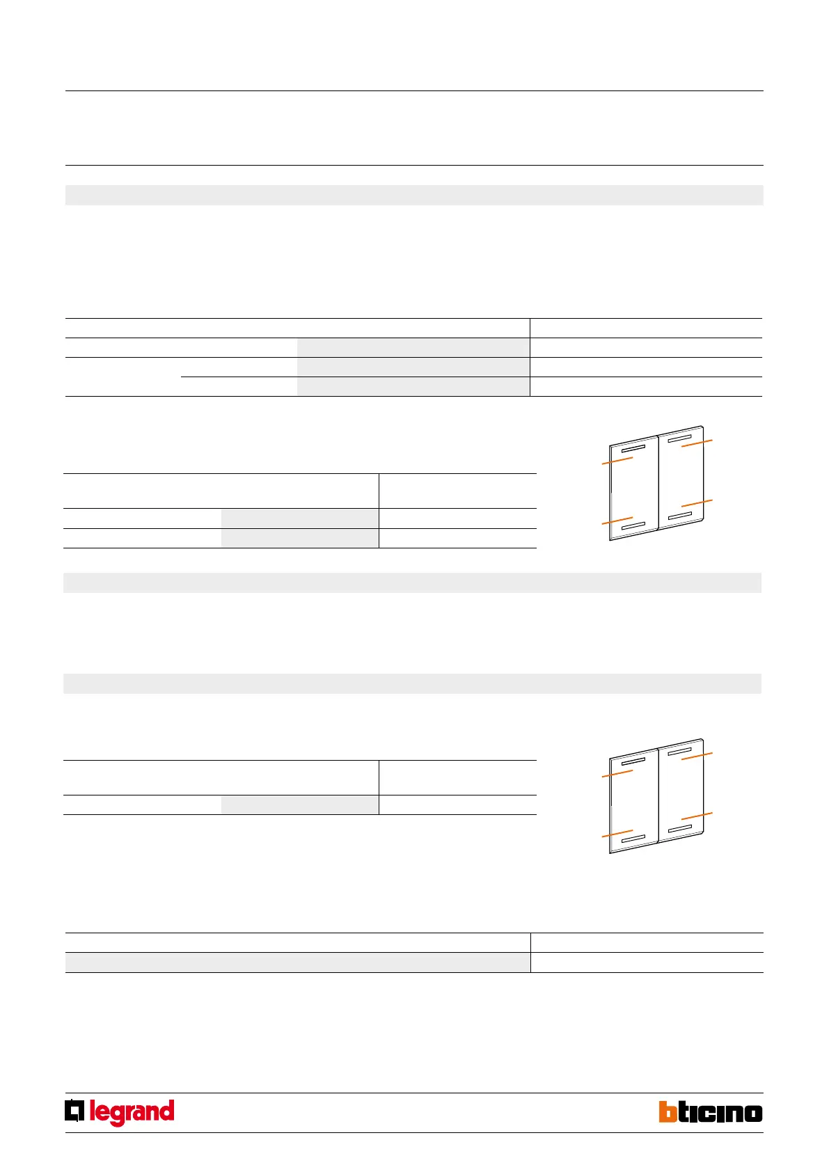
5. Programmed scenario activation
Virtual configuration (MYHOME_
Suite)
Physical configuration
Top button 0-31 SPE=0 M=CEN
Bottom button 0-31 SPE=0 M=CEN
Virtual configuration (MYHOME_Suite) Physical configuration
Addressing type
Room 0-10 A=1-9
Lighting point 0-15 PL=1-9
Enabling buttons for sending a command to the scenario programmer MH200N.
The address of the assigned command in positions A and PL must be unique and match
the scenario to be activated. The control can be connected at any point in the system
(local bus or riser).
5.1 Addressing
5.2 Mode
6. Plus programmed scenario activation
To configure the number 1 - 2047 of the scenario and of the buttons 0 - 31 on the
control device, use MYHOME_Suite virtual configuration
7. Video door entry functions
7.1 Unlocking control
7.1.1 Addressing
Virtual configuration (MYHOME_Suite) Physical configuration
Same command level SPE=7 M=1
Note 1): Define the address P (two digits) of the external unit whose lock is to be controlled with
button T3 (bottom left).
Button T4 (bottom right) controls the lock of the external unit P+2. Button T1 (top left) controls
the lock of the external unit P+1 and button T2 (top right) that of the external unit P+3.
Addressing type Virtual configuration (MYHOME_
Suite)
Physical configuration
Address of the external unit 0-95 A=1-9 PL=1-9
1)
Destination level
To set the Riser or Backbone destination level use MYHOME_Suite virtual configuration
Special control
MQ00285-c-EN 09/06/2014