302
1
C1 C2
1
1 2 3 4
2 43
2
3
4
C1 C2
F430/2F430/2
Description
By means of internal relays, this device executes the controls received from the central
unit or the probe. It is needed to control loads such as motorised valves, pumps and
electric radiators.
It has two independent relays which can be used to control two distinct loads with
ON/OFF function and to control a single load with open/close function.
To manage open/close loads the actuator must be congured with the logical interlock
of the two relays and contact C1 must be considered for the opening control and contact
C2 for the closing control.
Technical data
- Power supply from SCS BUS: 27 Vdc
- Operating power supply with SCS BUS: 18 – 27 Vdc
- Maximum absorption relays activated individually): 25.5 mA
- Absorption (relays activated with interlock): 14 mA
- Absorption in stand-by: 9 mA
- Current load of individual relays: 6 A (resistive) e.g. electric radiators
2 A (inductive) e.g. solenoid valves, pumps
- Maximum power consumption: 1.7 W
- Operating temperature: 5 – 40 °C
- Size: 2 DIN modules
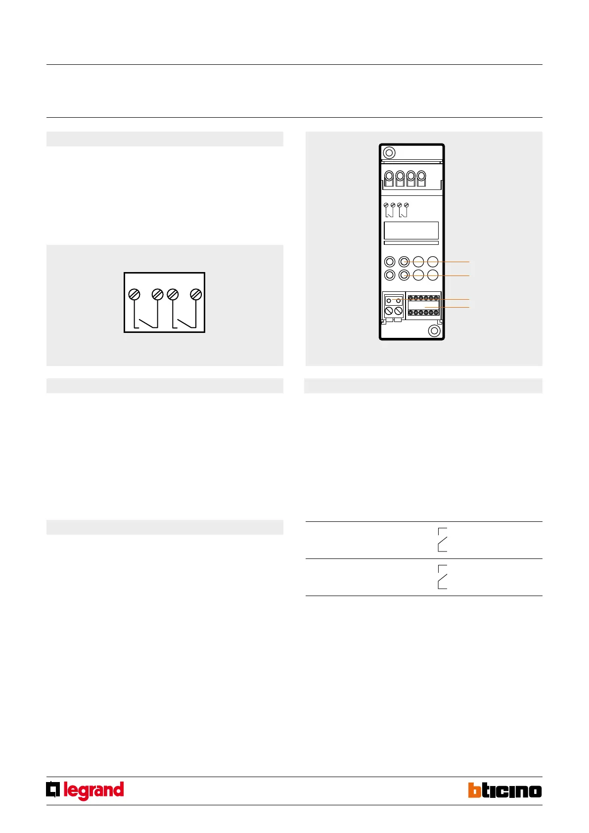
Front view
Conguration
The item must be congured by connecting the two congurators identifying the
actuator address and the number of the zone they belong to the ZA and ZB sockets.
In practical terms, the operation is the same as the one performed for the probe, during
the denition of the zone.
A probe and an actuator belonging to the same zone will require the same numeric
congurators in the ZA and ZB sockets. On the front of the two-relay actuator are ve
sockets dedicated to the congurators:
ZA, ZB1, N1, ZB2, N2. The conguration sockets are distributed on the two relays in
the following way:
ZA ZB1 Relay 1 zone address
N1 Relay 1 progressive zone address
ZA ZB2 Relay 2 zone address
N2 Relay 2 progressive zone address
The two relays on the device are independent, and may be used to activate two separate
loads with ON/OFF function, such as: pumps, on/o type motorized valves, and electric
radiators. The diagram shows the correspondence between the congurator sockets and
the relay contacts.
Legend
1. C1 clamps 1 - 2 relay forcing pushbutton
C2 clamps 3 - 4 relay forcing pushbutton
The forcing pushbuttons do not operate if the OFF congurator is connected to the
ZB1 or the ZB2 congurator sockets.
2. Yellow LEDs for notication of activation of the corresponding relays.
3. Congurator socket.
4. Removable clamp for BUS connection SCS.
congurator
socket
RL1
ZA
ZB1
N1
1
2
C1 contact
RL1
congurator
socket
RL2
ZA
ZB2
N2
3
4
C2 contact
RL2
The operation of one of the two relays may be excluded. To do this, connect the OFF
congurator to the socket corresponding to ZB1 or ZB2. The two relays may also be
used to control a single load with OPEN/CLOSE function, such as, for example, solenoid
valves with opening and closing control. For the management of these loads, it will be
necessary to congure the actuator with logic relay interlocking, connecting the same
numeric congurator both to ZB and N, therefore ZB1=ZB2 and N1=N2. In using the
contacts, consider contact C1 for the opening control and C2 for the closing control. A
relay congured in zone 00 operates as a circulation pump actuator; for this function,
the two relays cannot be congured as interlocked.
Actuator 2 relays
MQ00184-c-EN 29/04/2014
 Loading...


