312
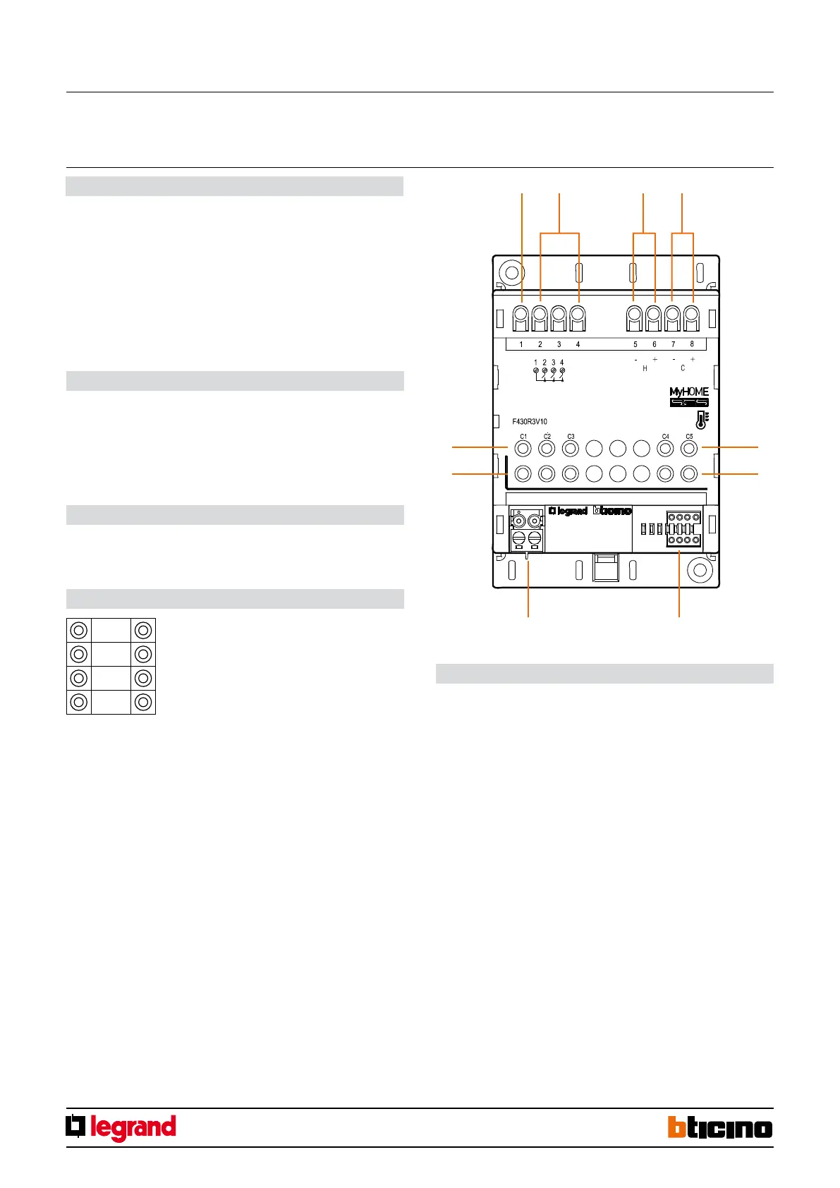
F430R3V10
MM00781-a-
2
8 7
5 5
6 6
3 41
Legend
1.
Common contact
2. Fan-coil fan speed
3. Output H 0-10 V heating
4. Output C 0-10 V cooling
5. Pushbuttons for the complete opening/closure of the valves, and for changing the
fan speed
6. LED
7. Configurator socket
8. BUS
DIN modularity actuator to be used in temperature control systems for the control of
2-tube or 4-tube fan coils with 0-10 V valves
It has with 3 relays for the managementof the fan-coil fan, and 2 x 0-10 V outputs for
the control of the valves.
In systems with 2-tube fan-coils the H output is used both for heating and cooling.
In systems with 4-tube fan-coils the H output must be used to control the heating valve,
while the C output for the cooling valve.
The LEDs indicate respectively the status of the valves and the active speed of the fan-
coil fan.
Description
Power supply from SCS BUS: 18 – 27 Vdc
Stand by absorption: 20 mA
Max. absorption: 60 mA
Operating temperature: (+5) – (+40) °C
Maximum current supplied by each 0-10 V output: 1 mA
Maximum driven power for the relays: 4A (resistive); 1A (inductive)
Technical data
4 DIN modules
Dimensional data
Fan-coil actuator with 0-10 V valves
EN
ZA, ZB = Actuator address
N = Progressive zone number
LOAD = Type of load
LOAD = 0; control of one 4-tube fan-coil with
0-10 V valves
LOAD = 1; Control of one 2-tube fan-coil with
0-10 V valves
Configuration
ZA
ZB
N
LOAD
Virtual configuration using the MyHOME_Suite software:
The device can be configured remotely only if not already physically configured. The
configuration is completed using version 1.3 or higher of the MyHOME_Suite software,
which can be downloaded from the website www.homesystems-legrandgroup.com.
24/09/2013