447
PLN Z P M A
BT00678-a
391670
PI PLAPN
S
L
A
-EN
TECHNICAL SHEETS
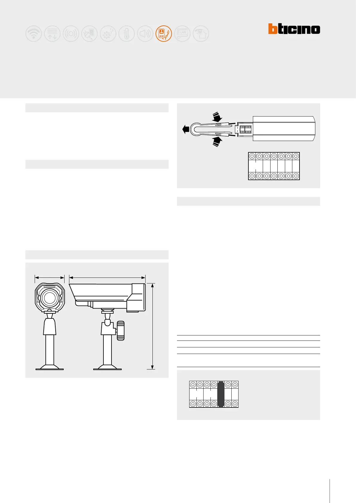
Dimensional data
Conguration
Description
2-wire compact outdoor (IP65) colour camera.
It can be used for video monitoring system installations, or for turning audio systems
into video systems, using a separate camera.
WARNINGS : do not point the camera towards the sun or towards light sources.
Technical data
Power supply from SCS BUS: 18 – 27 Vdc
Enclosure: aluminium
Sensor: 1/3” CMOS colour
Stand by absorption: 5 mA
Max. operating absorption: 65 mA
Lens: f: 6 mm; F: 2.3 mm
Image elements: 628 (H) x 586 (V)
Horizontal resolution: 330 TV lines at the image centre
Minimum illumination: 2 Lux F=2.0
Operating temperature: (-20) – (+70) °C; RH 95% max
Protection index: IP65
Outdoor 2-wire
colour camera
The device must be physically congured in terms of:
P – Camera address
The congurator assigns to the camera the address inside the apartment.
N – Address of the handset called in case of alarm
Z – Zone of the alarm system the camera is associated to
M – Mode of operation when a camera is switched on
Each time a camera is switched on (call, selfswitching on, alarm) the MY HOME
actuator and the scenario congured in A and PL are activated. When the camera is
switched o, the associated actuator also switches o, while the scenario remains
active.
If an actuator used by the automation system is also associated to the camera, the
actuator will switch itself o when the camera is switched o, even if it was already
on when the camera came on. To avoid this problem, the load should be activated
using an actuator item F411/2, conguring dierent PL and setting the contacts
with parallel connection.
M A/PL
M = 0 Address of the SCS control device associated to the camera
M = 1 - 9 Address of the scenarios module associated to the camera
M = SLA Conguration of the audio entrance panel associated to the camera
(see following details)
Pi - Pn = range of audio EP associated to the camera (max.5)
M = SLA
PI - PN = Audio entrance panels associated to the camera (max. 5)
PI = Address of rst associated EP
PN = Address of last associated EP
A/PL = Address of the SCS control associated to the camera