71
N
L
M
L1
L2
N
F401
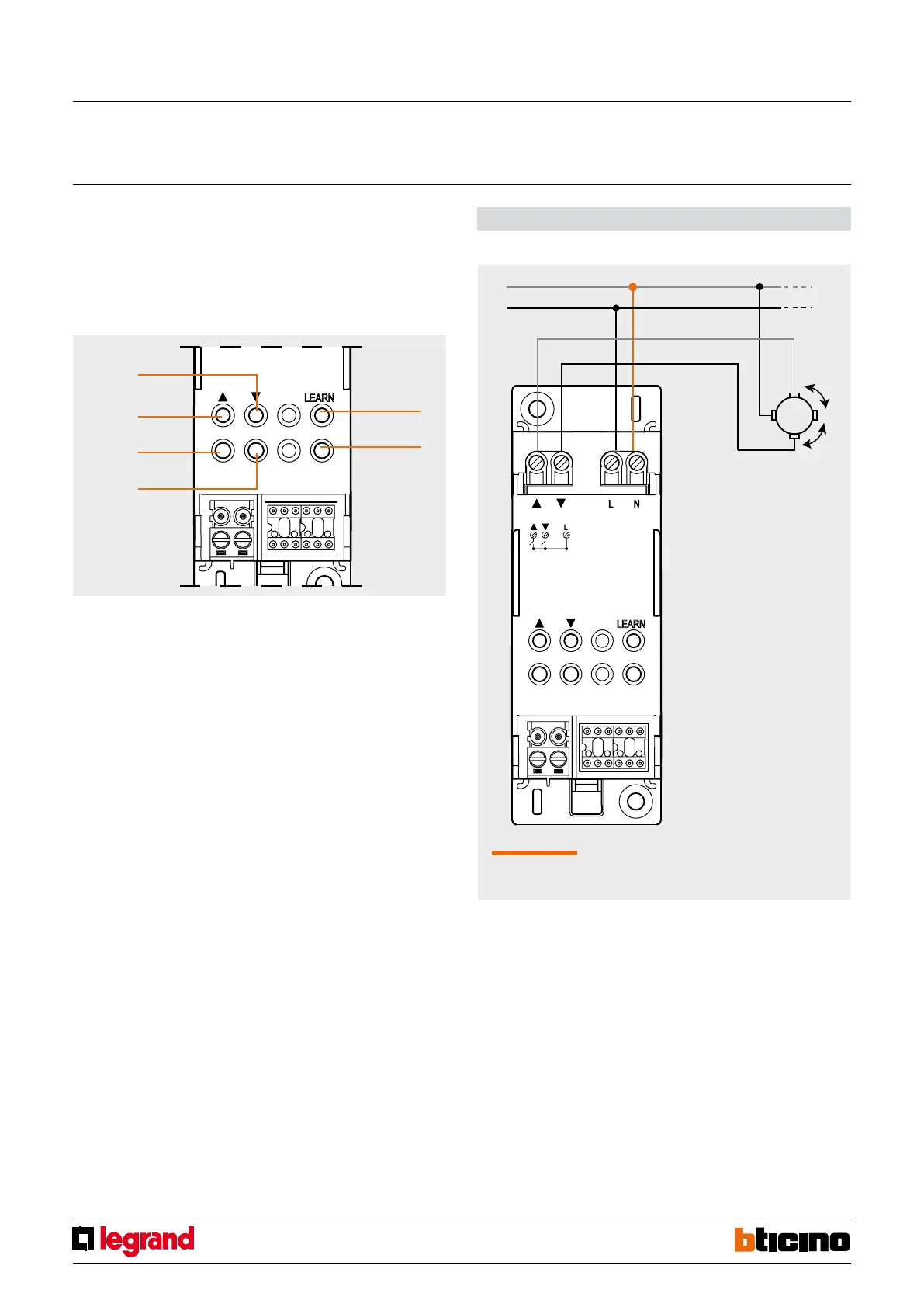
UP
PUSHBUTTON
UP LED
DOWN
PUSHBUTTON
Configuration
pushbutton
LED
configuration
DOWN LED
Rolling shutter actuator
MQ00593-c-EN 09/06/2014
Calibration of the shutter position
This operation is necessary for correct operation of the actuator, which will have to save
the shutter maximum opening and closing positions.
If no calibration is performed, the actuator cannot be managed by the control devices,
but only locally, by pressing the corresponding front pushbuttons.
Depending on the type of motor to manage, different procedures will have to be
followed:
Automatic calibration
It applies to standard motors.
1. Press the configuration pushbutton for at least 3 seconds. The corresponding LED comes on.
2. Press and release the “UP” pushbutton. The shutter moves upwards and the “UP” LED
comes on.
3. Once the shutter has reached the maximum opening position, it will automatically
start to move downwards until fully closed. The “DOWN” LED comes on. During this
stage, the actuator measures and saves the time it takes the shutter to close (*).
4. The shutter will then automatically start moving upwards, until the maximum
opening position has been reached. The “UP” LED comes on. During this stage, the
actuator measures and saves the opening time.
5. The switching off of the LED associated to the configuration pushbutton and of the
“UP” LED confirm the completion of the calibration procedure.
Note (*): If what described at point 3 is not automatically completed, proceed with the
manual calibration of the device, and connect configurator 1 to the Type socket of the
actuator.
Manual calibration
It applies to standard or pulse motors.
1. Press the configuration pushbutton for at least 3 seconds. The corresponding LED comes on
2. Press and release the “UP” pushbutton. The shutter moves upwards and the “UP” LED
comes on.
3. Once the shutter has reached the maximum opening position, press the “DOWN”
pushbutton. The shutter will move downwards, and the “DOWN” LED will come on.
During this stage, the actuator measures and saves the time it takes the shutter to close
4. When the shutter is fully closed, press the “UP” pushbutton. The shutter moves
upwards and the “UP” LED comes on. During this stage, the actuator measures and
saves the time it takes the shutter to open
5. Once the shutter maximum opening position has been reached, press the “DOWN”
pushbutton again. The “UP” LED will turn off.The calibration procedure has now
been completed; the LED associated to the configuration pushbutton will turn off, to
confirm that the operation has been completed successfully.
WARNING: The calibration precision, and therefore the control of the shutter position,
depends on the accuracy with which the limit switch positions are manually detected
during the calibration itself.
For standard motors with mechanical limit stop
connect the neutral conductor
Pulse motor
For the connection refer to the indications supplied with the motor interface.
Standard motor with electronic limit switch
Wiring diagram


 To Next Page