Electrophotographic process (EP process)
Printhead
The printhead scans the photo conductor drum surface with a laser beam. It consists of the following
components:
• Laser diode (LD) card assembly
• Oscillator
• Start of scan card assembly
When a laser beam is scanned across the photoconductor drum surface from one end to the other while turning
on and o the beam, one line of latent image is created. If the scanning by the laser beam is repeated while
rotating the drum, a two-dimensional image is created. The resolution in the scanning direction (from right to
left) is determined by the rotational speed of the printhead motor, depending on how quickly the laser is
adjusted. The resolution in the process direction (from top to bottom) is determined by the rotational speed of
the printhead motor. The higher the scanning speed becomes, the sooner the scanning of the next row can be
started.
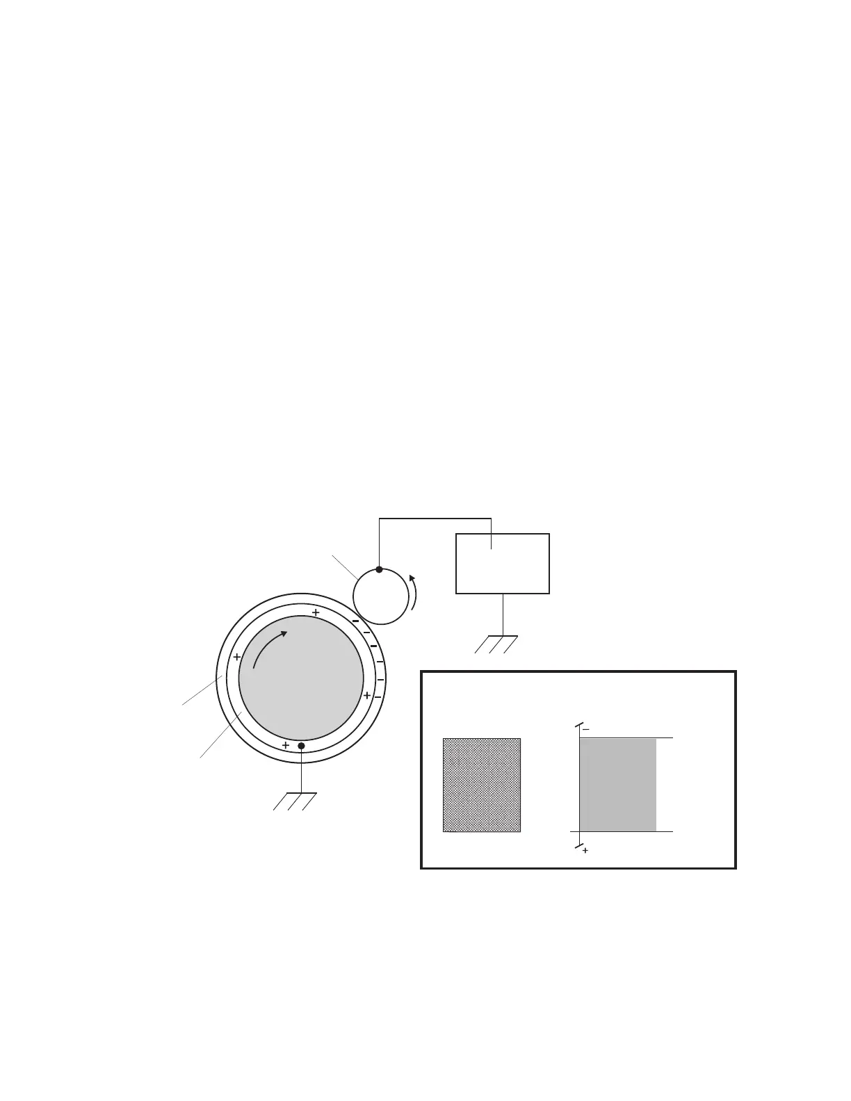
Step 1: Charge
During the charge step, voltage is sent from the HVPS to the charge roll beside the photoconductor. The charge
roll applies a uniform negative charge over the entire surface of the photoconductor to prepare it for the laser
beam.
HVPS
(-VDC)
(-VDC)
Ground
Conductive Tube
Photoconductive
Surface
0V
-VDC value
DRUM
Drum Surface
Voltage
Drum Surface
Image
Ground
Charge roll
4514-6xx
Theory of operation
372