Vertiv
™
| Liebert® EXL™ 625-1100kVA Installation Manual | Rev. 3 | 02/17 18
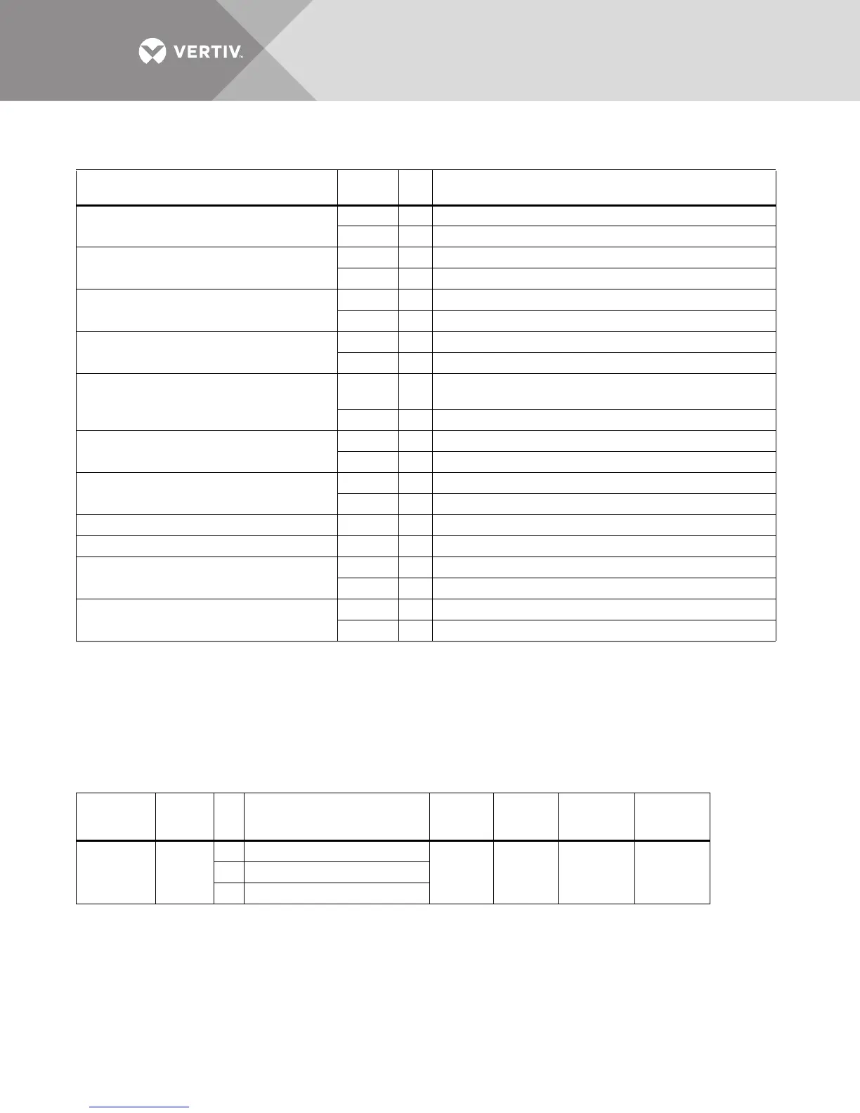
2.5.1 Dry Contacts
Table 2 UPS Digital Inputs
Item
Terminal
Block Pin
Connect to
(Description of External Item)
Maintenance Bypass Breaker (MBB)
TB2 1 MBB Aux Contact, Closed = Circuit Breaker is Closed
TB2 2 MBB Aux Contact Common
Maintenance Isolation Breaker (MIB)
TB2 3 MIB Aux Contact, Closed = Circuit Breaker is Closed
TB2 4 MIB Aux Contact Common
Bypass Isolation Breaker (BIB) - Dual Source Input
None - Single Source Input
TB2 5 BIB Aux Contact, Closed = Circuit Breaker is Closed
TB2 6 BIB Aux Contact Common
Rectifier Feed Breaker (RFB) - Dual Source Input
UPS Input Breaker (UIB) - Single Source Input
TB2 7 RFB Aux Contact, Closed = Circuit Breaker is Closed
TB2 8 RFB Aux Contact Common
Reserved for Internal Use (SMS)/
Module Output Breaker (1+N)
TB2 9
Reserved for Internal Use (SMS)/MOB Aux Contact,
Closed = Circuit Breaker is Closed (1+N)
TB2 10 Reserved for Internal Use (SMS)/MOB Aux Contact Common (1+N)
REPO/EPO (N.O.)
TB2 11 REPO Switch, Normally Open Contact
TB2 12 REPO Switch, Normally Open Common
REPO/EPO (Form-C or N.C.)
TB2 13 REPO Switch, Normally Closed Contact
TB2 14 REPO Switch, Normally Closed Common
REPO/EPO (Form-C) TB2 15 REPO Switch, Normally Open Contact
REPO/EPO Additional Common TB2 16 REPO Switch, Normally Closed Common
Key Status
TB2 17 Key Status Switch, Closed = Key Released
TB2 18 Key Status Switch, Common
On Generator
TB2 19 On Generator (NO)
TB2 20 On Generator (COM)
1. All contacts have:
Maximum voltage: 24VDC
Maximum current: 10mA
Wire range: #14-22AWG
Maximum length: 500' (150m)
2. All external wire furnished by others
3. All wiring must be in accordance with national and local electrical codes
4. If using REPO/EPO with Form-C contacts, Pins 13-15 must be used
5. If using REPO/EPO with normally closed (N.C.) contacts only, a jumper must be placed across Pins 15 and 16
Table 3 UPS Output
Item
Terminal
Block
Pin
Connects to
(Description of
External Item)
Maximum
Voltage
Maximum
Current
Wire
Range
Maximum
Length
SKRU Enable TB3
1SKRU Enable Common
120VAC 1A #14-22 AWG 164ft. (50m)2 SKRU Enabled, Contact is Open
3 SKRU Enabled, Contact is Closed
1. To prevent signal interference, low-voltage (<48V) and low-current (5A) cable groups should be run in separate, grounded conduit from
high-voltage or high-current cable groups.
2. All external wire furnished by others.
3. All wiring must be in accordance with national and local electrical codes.