Vertiv
™
| Liebert® EXL™ 625-1100kVA Installation Manual | Rev. 3 | 02/17 20
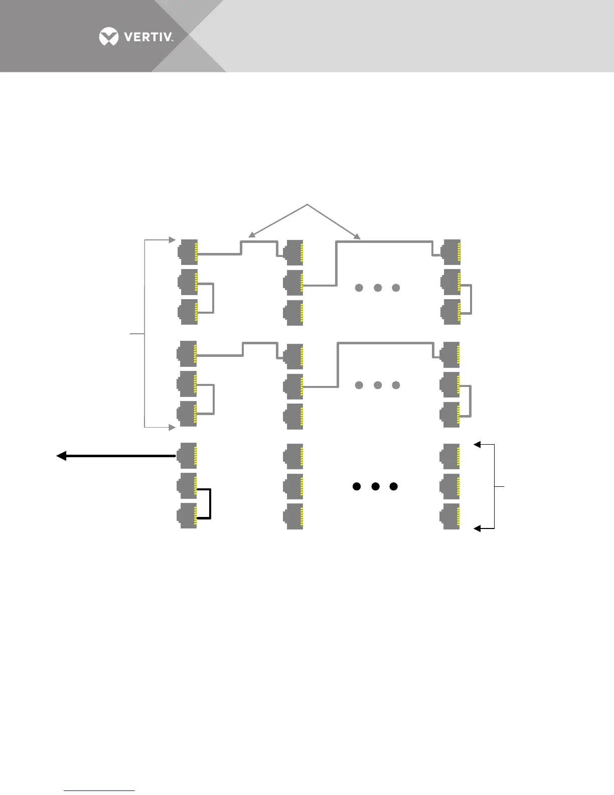
2.6 DIGITAL LBS
The Load Bus Sync interface enables independent UPS units to remain in sync when operating on battery or
when supplied by unsynchronized input sources.
Digital LBS cables that connect the module to the system are connected to Terminals J7-J9 customer
connections on the control drawer. See Figure 9.
Figure 9 LBS connectivity
2.7 GROUNDING
2.7.1 Three-Wire Input connections
This module must NOT be used when single-phase loads are directly connected to the UPS. Note that whenever
the UPS module transfers to or from bypass, two AC sources (UPS output and bypass) are briefly connected
together and circulating current must flow. In this configuration, the current flows through the ground path and
may trip ground fault interrupters (GFI’s), distorting the output voltage waveform. Proper adjustment of GFI’s is
necessary to avoid unwanted tripping. The time delay should be set to at least 0.2 seconds to prevent tripping
when the UPS performs a transfer or retransfer operation.
NOTICE
Failure to set the ground fault interrupters properly could cause loss of power to the critical load.
2.7.2 High Resistance Grounding
Contact your Vertiv
®
representative or the factory to determine whether the Liebert EXL is compatible with the
specific type of HRG system involved.
Reserved
for LBS
Reserved for
MMS/1+N
J1
J9
J8
J7
J6
J5
J4
J3
J2
J1
J9
J8
J7
J6
J5
J4
J3
J2
UPS 1 UPS 2 UPS n
Cat 6 Cable
NC
NC
To next set of
modules, UPS1-J7
NC
NC
NC
NC
NC
NC
Cat 6 Cable
J1
J9
J8
J7
J6
J5
J4
J3
J2