Vertiv
™
| Liebert® EXL™ 625-1100kVA Installation Manual | Rev. 3 | 02/17 44
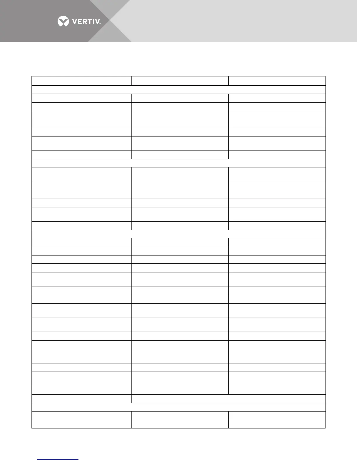
5.0 SPECIFICATIONS
Table 13 Liebert EXL UPS specifications
Model Size
625-800kVA 1000-1200kVA
Input Parameters
Input Voltage to Rectifier, VAC 480V 3-phase, 3-wire 480V 3-phase, 3-wire
Input Voltage to Bypass, VAC 480V 3-phase, 3-wire 480V 3-phase, 3-wire
Input Voltage Range, VAC +10% to -30% +10% to -30%
Input Frequency, Hz 60 60
Permissible Input Frequency Range, Hz 55 to 65 55 to 65
Reflected Input THDi, Nominal Voltage, Full
Load, %
<5% <5%
Power Walk-In, sec 1 to 30 (selectable) in 1 sec. Increments 1 to 30 (selectable) in 1 sec. Increments
Battery & DC Parameters
Battery Type
VRLA (Valve Regulated Lead Acid) or FLA
(Flooded Lead Acid)
VRLA (Valve Regulated Lead Acid) or FLA
(Flooded Lead Acid)
Nominal Battery Bus, VDC 480V 480V
Battery Float Voltage, VDC 540V 540V
Minimum End of Discharge Voltage, VDC 384V (for VRLA / Flooded Lead Acid) 384V (for VRLA / Flooded Lead Acid)
DC Ripple Voltage in Float & Const V Ch.
Mode, %
<1 (RMS value) < 3,4% Vpp <1 (RMS value) < 3,4% Vpp
Temperature Compensated Battery Charging Optional (with temperature probe) Optional (with temperature probe)
Output Parameters
Inverter Type IGBT-based Sine Wave PWM Controlled IGBT-based Sine Wave PWM Controlled
Output Power, kW 625 | 750 | 800 1000 | 1100 | 1200
Output Voltage, VAC 480V 3-ph, 3-wire 480V 3-ph, 3-wire
Output Voltage Regulation, % < 1% (3-phase RMS average) < 1% (3-phase RMS average)
Output Voltage Regulation (50% Unbalanced
Load)
< 2% (3-phase RMS average) < 2% (3-phase RMS average)
Output Frequency, Hz 60 60
Output Frequency Regulation, % ± 0.1 ± 0.1
Output THDv Linear Load at Nominal Voltage,
%
<3% <3%
Output THDv at Nominal Voltage Including a
100kVA Non-Linear Load per EN 62040-3, %
6% (max) 6% (max)
Capacity to Handle High Crest Factor Load 3:1 3:1
Capacity to handle Step Load, % 0-100 or 100-0 0-100 or 100-0
Step Load Transient Recovery (linear loads),
%
IEC 62040-3, Section 5.3.1 Figure 1 IEC 62040-3, Section 5.3.1 Figure 1
Unbalance Loads Current Capacity 100% of nominal phase current 100% of nominal phase current
Load Power Factor Supported (Without
Derating)
0.7 Leading to 0.7 Lagging 0.7 Leading to 0.7 Lagging
Voltage Displacement, ° (Electrical Degree) 120° ±1° (with 50% unbalanced load) 120° ±1° (with 50% unbalanced load)
Overload Conditions, % FL See Figures 31, 32 and 33
Physical Parameters and Standards
Width, in (mm), With Static Bypass 123.6 (3140) 170.7 (4335)
Depth, in (mm) 34.4 (874) 34.4 (874)