Vertiv
™
| Liebert® EXL™ 625-1100kVA Installation Manual | Rev. 3 | 02/17 32
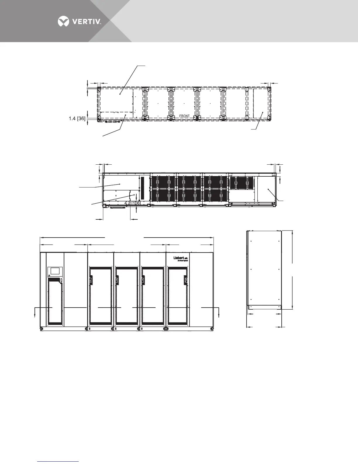
Figure 19 Outline Drawing, 1000-1200kVA Liebert EXL UPS, SMS and 1+N multi-module unit
NOTES
1. All dimensions are in inches (mm).
2. 24" (610) minimum clearance above unit required for air exhaust;
36" (914) front access required for service.
3. Keep cabinet within 15 degrees of vertical while handling.
4. Top and bottom cable entry available through removable access plates.
Remove, punch to suit conduit size and replace.
5. Unit bottom is structurally adequate for forklift handling.
6. Control wiring and power wiring must be run in separate conduits.
7. All wiring is to be in accordance with national and local electrical codes.
8. Width dimension includes side panels. Subtract 1.4" (35mm) when removing both side panels.
9. See technical information drawing for shipping split weights.
77.5"
(1969mm)
47"
(1193mm)
47"
(1193mm)
26.7"
(679mm)
To Frame
1.3" (33mm)
To Frame
2"
(50mm)
1.3" (33mm)
To Frame
3" (77mm)
To Frame
2.4" (60mm)
To Frame
2.4" (60mm)
To Frame
1.3" (33mm)
170.7" (4335mm)
76.7" (1949mm)
33.5"
(850mm)
34.4"
(874mm)
TOP
FRONT
INPUT
FRONT
RIGHT SIDE
With
Accent Strip
See
Bottom
View
U46-12C-2001
Rev. 2
To Frame
Typical Opp. Side
Bypass/Output
Cable Exit, Area
With Panel Removed
28.7" x 14.3"
(730 x 364mm)
Bypass/Output
Cable Exit, Area
With Panel Removed
25.4" x 15.7"
(645 x 399mm)
Low-Voltage Cable
Entry/Exit, Area
With Panel Removed
10.6" x 7.9"
(269 x 7.9mm)
Low-Voltage Cable
Entry/Exit, Area
With Panel Removed
6.0" x 32.2"
(152 x 819mm)
Rectifier/DC
Cable Entry, Area
With Panel Removed
14.7" x 33.3"
(373 x 846mm)
Rectifier/DC Cable Entry,
Area With Panel Removed
22.7" x 32.2" (577 x 819mm)
Section A (Top Looking Down)
BOTTOM VIEW
A
A
CORE CORE CORE OUTPUT/BYPASS