Vertiv
™
| Liebert® EXL™ 625-1100kVA Installation Manual | Rev. 3 | 02/17 41
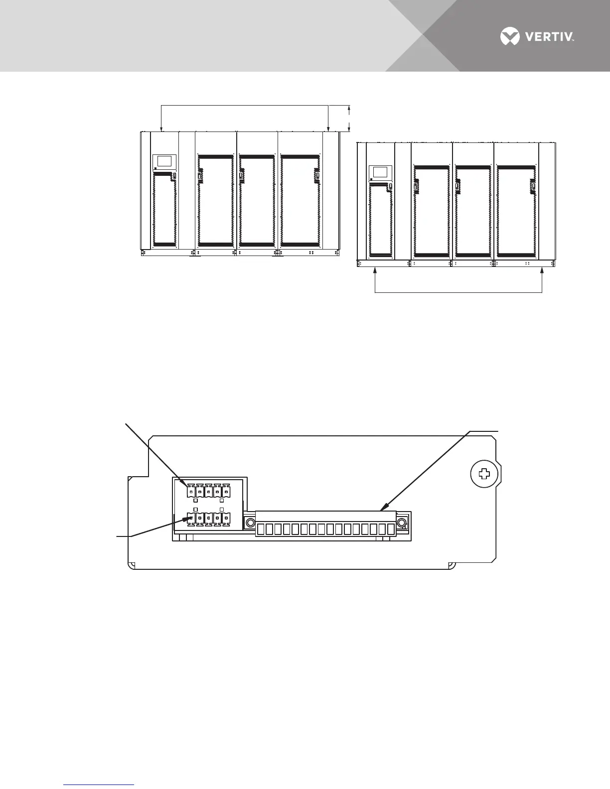
Figure 28 Cabling for single input configuration
Figure 29 Optional Input Contact Isolator Board
NOTES
1. 24" (610) minimum clearance above the unit is required for air exhaust.
2. Top and bottom cable entry is available through removable access plates. Remove, punch to suit conduit size and replace.
3. All wiring is to be in accordance with national and local electrical codes.
4. See Table 18 for cable sizing
5. Connections between the rectifier and bypass busbars are supplied by others.
6. Based on NEC 408.56 minimum spacing, all live parts, including lugs, must be at least 1 inch (25.4mm) from any other live part
from a different phase or the chassis frame. If lug stacking is required, the method of stacking and required minimum spacing is
the responsibility of the installing contractor and the authority having jurisdiction. See Figures 22 - 26 for busbar details.
625-800kVA unit
shown, similar
configuration for
1000-1200kVA unit
Output/Bypass
Core
Input
Core
Output/Bypass
Core
Input
Core
Note 1
1. Customer control wiring connection points are Terminals 1 through 16 (see Table 11).
2. Customer-provided, normally open dry contacts for user alarm messages.
3. All control wiring (by others) must be run separate from power wiring.
4. Signal voltage: 100mA @ 12VDC.
5. Maximum cable length is 500 ft. (152m) with #16AWG and flexible stranded cable.
6. All wiring must be in accordance with national and local electrical codes.
P99
J51
P66
12345678910111213141516