Vertiv
™
| Liebert® EXL™ 625-1100kVA Installation Manual | Rev. 3 | 02/17 37
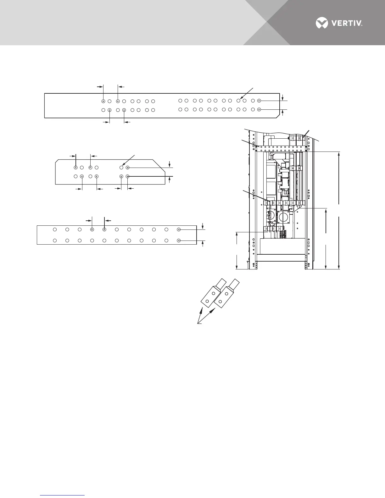
Figure 24 Output and bypass terminal detail, 625-800kVA Liebert EXL UPS, SMS and 1+N multi-module unit
Notes:
1. Control wiring and power wiring must be run in separate conduits
2. All wiring is to be in accordance with national and local electrical codes.
3. See Page 1, Drawing U46-8E-3200A and Page 2, Drawing U46-8E-3200B.
4. Based on NEC 408.56 minimum spacing, all live parts, including lugs,
must be at least 1" (25mm) from any other live part from a different phase
or the chassis frame. If lug stacking is required, the method of stacking
and required minimum spacing is the responsibility of the installing
contractor and authority having jurisdiction.
U46-8E-3200C
Rev. 3
Dual Hole Lug
Pad Width (Max.)
1.75" (44mm)
18.5"
(469mm)
30.3"
(770mm)
58.4"
(1484mm)
RIGHT SIDE VIEW
OUTPUT/BYPASS
6
5
4
#4 Bypass Input Busbar 38.2 x 4 x .25
2.36"
(60mm)
Typ.
2.36" (60mm)
Typ.
Ø .56" (14mm) Typ.
1.43" (36mm)
2.36"
(60mm)
Typ.
2.36" (60mm)
Typ.
Ø .56" (14mm) Typ.
1.44" (37mm)
1.0" (25mm) Typ.
#5 Phase Output Busbar 17.7 X 4 X .25
1.97"
(50mm)
Typ.
Ø .56" (14mm) Typ.
1.75" (44mm)
#6 Output Ground Busbar 25.4 x 3 x .25