Vertiv
™
| Liebert® EXL™ 625-1100kVA Installation Manual | Rev. 3 | 02/17 43
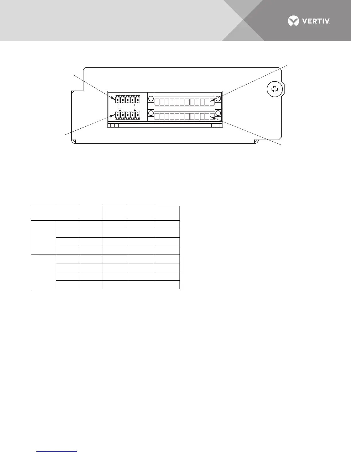
Figure 30 Control wiring, Programmable Relay Board
Table 12 Programmable Relay Board pinout
Terminal
Block Channel Pin No. Common
Normally
Closed
Normally
Open
J71
CH1 1-3 1 2 3
CH2 4-6 4 5 6
CH3 7-9 7 8 9
CH4 10-12 10 11 12
J72
CH5 1-3 1 2 3
CH6 4-6 4 5 6
CH7 7-9 7 8 9
CH8 10-12 10 11 12
1. Customer control wiring connection points are Terminals 1 through 12.
2. Programmable Relay Board option includes eight signal channels with one Form-C dry contact per channel (see Table 12).
3. All control wiring (by others) must be run separate from power wiring.
4. Contact ratings: 1A @ 30VDC or 125VAC @ 0.45A
5. Maximum cable length is 500 ft. (152m) with #16AWG and flexible stranded cable.
6. All wiring must be in accordance with national and local electrical codes.
P99
J71
P66
J72
123456 789101112
123456 789101112