Vertiv
™
| Liebert® EXL™ 625-1100kVA Installation Manual | Rev. 3 | 02/17 29
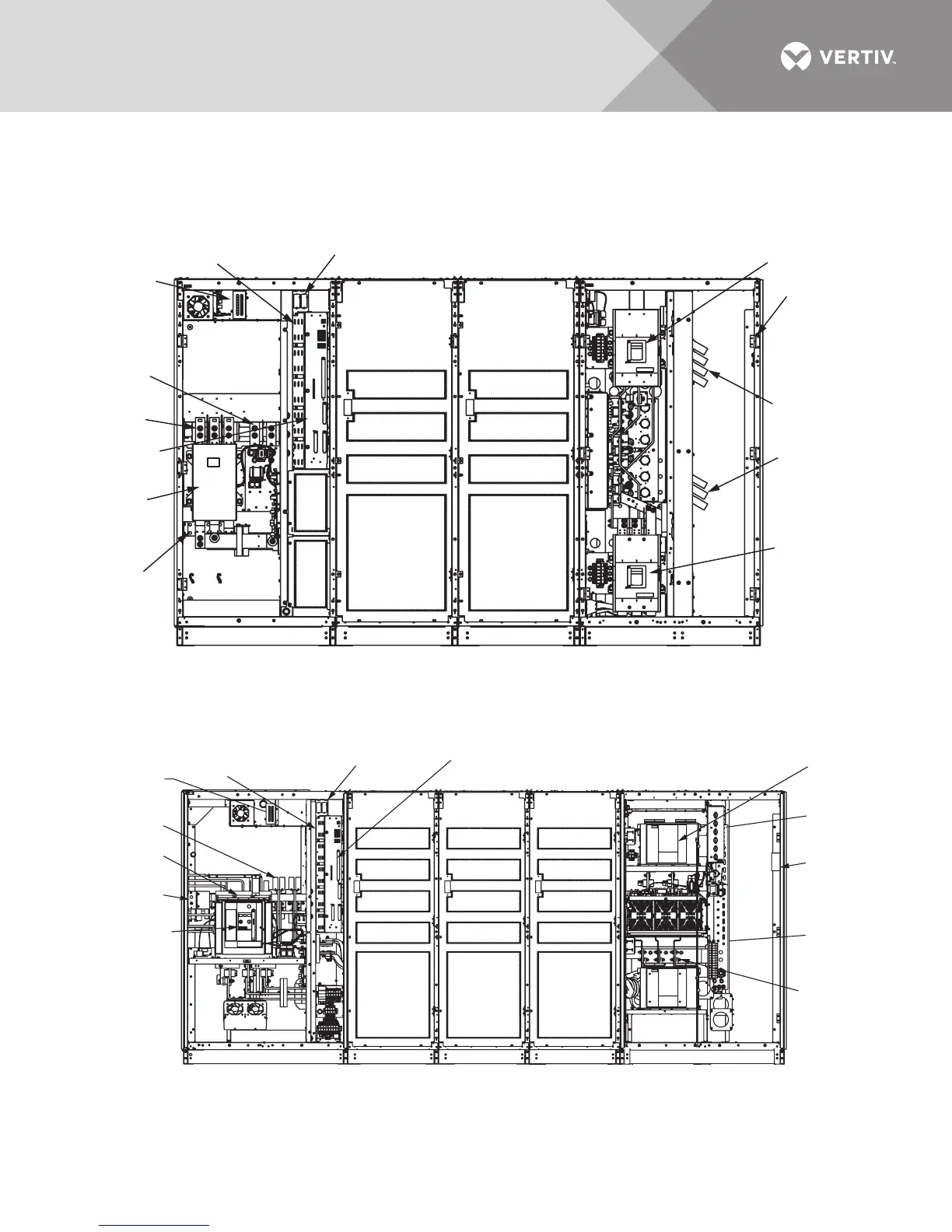
4.0 INSTALLATION DRAWINGS
Figure 14 Typical main components, 625-800kVA Liebert EXL UPS, SMS and 1+N multi-module unit
Figure 15 Typical main components, 1000-1200kVA Liebert EXL, SMS and 1+N multi-module unit
CORE
OUTPUT/BYPASS
CORE
U46-8C-2000
Rev. 5
DOORS AND INNER SKINS NOT SHOWN
Options Box
(5 Slots)
Liebert
IntelliSlot
Housings
Motor
Operated
Circuit
Breaker (CB1)
Module Output
Circuit Breaker
(CB2)
Backfeed
Circuit Breaker
(BFB)
Input
Ground
Control
Drawer
Input
Busbars
DC
Input
Output
Busbars
Bypass
Busbars
High-Voltage
Sense Test
Points
INPUT
Output
Ground
Busbar
Back Feed
Circuit
Breaker
(BFB)
Module
Output
Circuit
Breaker
(CB2)
Bypass
Busbars
Output
Ground
Busbar
Output
Busbars
Liebert IntelliSlot
Housings
Motor Operated
Circuit Breaker
(CB1)
Options
Box (5 Slots)
High-Voltage
Sense
Test Points
DC Input
Input
Busbars
Input
Ground
Control
Drawer
OUTPUT/BYPASSCORE CORE COREINPUT
U46-12C-2000
Rev. 3
DOORS AND INNER SKINS NOT SHOWN
The difference between an SMS and 1+N configuration is that the 1+N
has sharing inductors present behind CB2 (not visible in drawing).