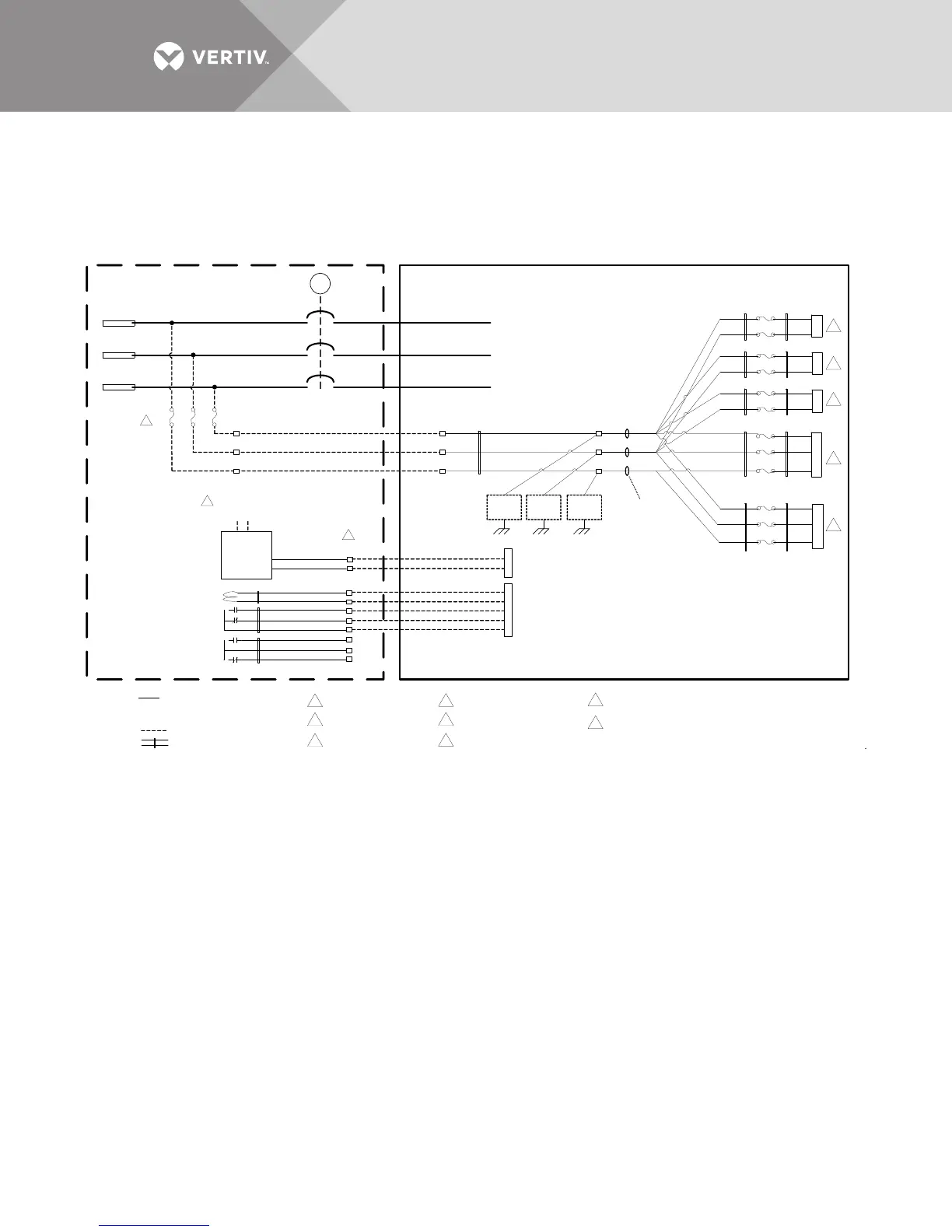
3.3 RECTIFIER INPUT BREAKER (RIB)
Unless noted otherwise, wiring
symbols used define the following:
Notes:
Twisted pair/triple control wiring.
Control wiring by others.
A
B
C
E
RIBX
60A
IN_LINE_A
IN_LINE_B
IN_LINE_C
F23
F22
V_IN_R_A
V_IN_R_B
V_IN_R_C
K2
K2_4
K2_5
TB7
TB6
TB7-4 (DRV)
TB7-3 (NO [CB CLOSED])
TB7-2 (NC [CB OPEN])
TB7-5 (+48V)
TB7-1 (COM)
Inside UPS Cabinet
RIBX UVR Coil
(48VDC)
RIBX Status
Contacts
RIBX Form C
Contact (Spare)
2x1
RIBX
240 VAC
(Supplied by
Switchgear Vendor)
TB6-10 (MTR_OP_CLOSE)
TB6-08 (MTR_OP_ENABLE)
Inside Switchgear
To Customer
Input Terminals
2x2
1x5
1x4
2x5
2x4
2x3
1 x 1
1 x 2
1 x 3
RIBX
2x6
2x8
2x7
1
1
Fuses should be 60A class
CC or J type time delay fuse
Connects to P101 on HV
Attenuator Burden Bd 518691 G1
Connects to Relay K2 for Fan Power
TB10
TB10-1
TB10-2
TB10-3
Electrical operator power provided by switchgear
vendor and shall be powered from line side of RIBX
These are terminals numbers on the switchgear
where x designates the unit number .
Example, for x=1, RIBX would be RIB1.
F24
K2_6
F51
F50
P101
P101_5
P101_3
F52
P101_1
F29
F28
P3
P3_5
P3_1
Connects to P3 on Power
Oring Bd 418581G1
F21
F20
K3
K3_1
K3_3
F46
F45
K4
K4_1
K4_3
Connects to Relay K3 for
DC bus precharge
Connects to Relay K4 for DC bus
precharge on 1200 kVA and above
TB11
PH A
TB12
PH B
TB13
PH C
EMIEMIEMI
EMI Cores
5 Turns
through Core
7
60A60A
12
12
12
8
12
12
12
12
12
12
12
12
12
12
12
12
2
3
4
5
6
7
8
Close
RIBX
Electrical
Operator
240 VAC
2
3
4
5
6