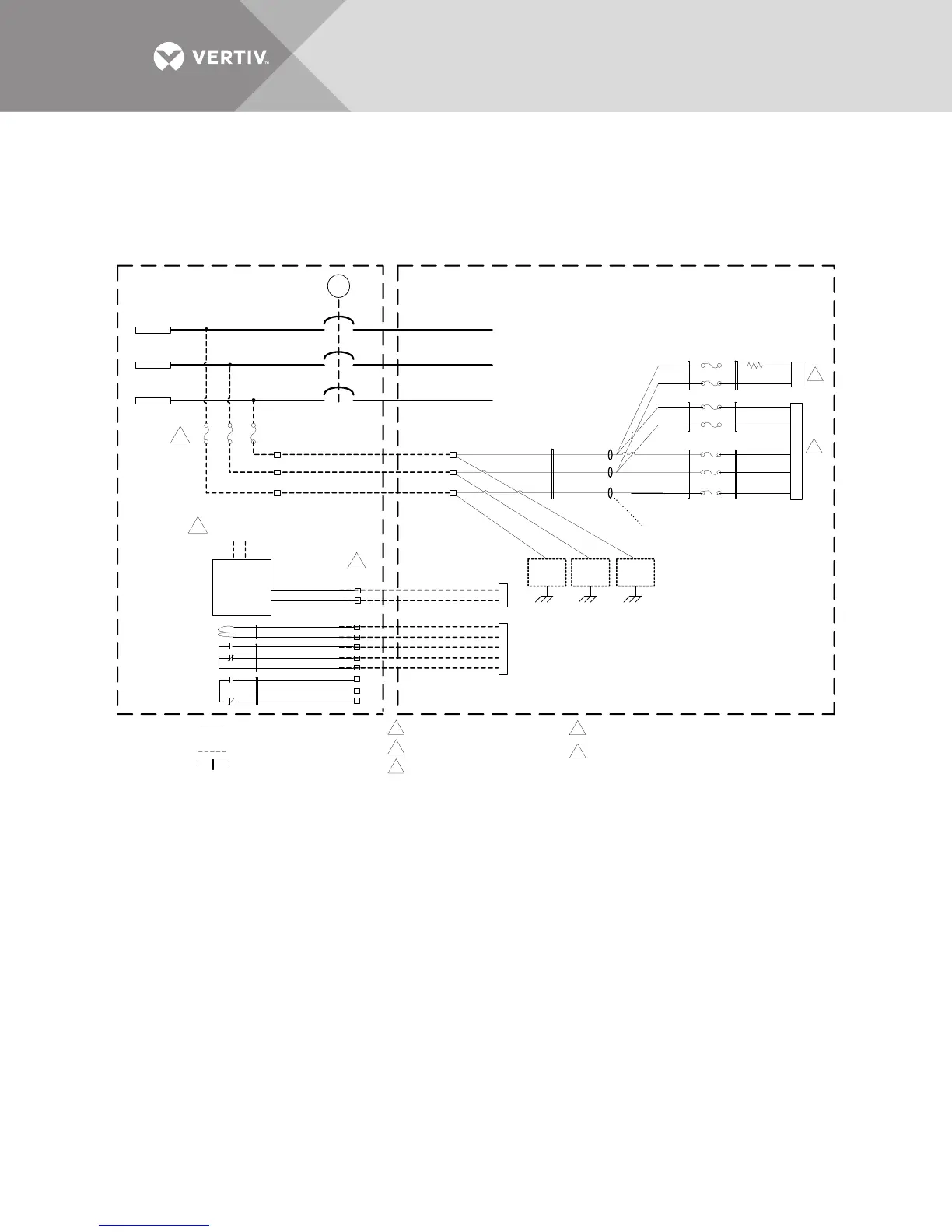
Unless noted otherwise , wiring symbols used
define the following :
Notes:
Twisted pair /triple control wiring
Control wiring by others
A
B
C
E
RBBX
5A
BYP_LINE_A
BYP_LINE_B
BYP_LINE_C
V_BYP_R_A
V_BYP_R_B
V_BYP_R_C
Inside UPS Cabinet
RBFBX ST Coil
(48VDC)
RBFBX Status
Contacts
RBFBX Form C
Contact (Spare)
240 VAC
Close
4x1
RBFBX
RBFBX
Electrical
Operator
240 VAC
(Supplied by
Switchgear Vendor )
Inside Switchgear
To Customer
Bypass
Terminals
4x2
3x5
3x4
4x5
4x4
4x3
3X1
3X2
3X3
RBBX
4x6
4x8
4x7
1
Fuses should be 5A class CC
or J type time delay fuse
TB14
TB14-1
TB14-2
TB14-3
Electrical operator power provided by switchgear
vendor and shall be powered from line side of RBFBX
5
These are terminals numbers on the switchgear where x designates
the unit number . Example , for x=1, RBFBX would be RBFB 1.
F64
F63
P300_3
P300_2
F65
P300_1
Connects to T4 Bypass PS Transformer
F38
F37
T4
T4_H4
2
F35
F34
P300
P300_7
P300_6
Connects to P300 for Bypass Voltage Sense
on HV Attenuator Bd 518691G1 and Bypass
Supply on Power Oring bd 418581 G1
R1
T4_H1
TB5
TB4
TB5-4 (DRV)
TB5-3 (NO [CB CLOSED])
TB5-2 (NC [CB OPEN])
TB5-5 (+48V)
TB5-1 (COM)
TB4-10 (MTR_OP_CLOSE)
TB4-08 (MTR_OP_ENABLE)
EMIEMIEMI
EMI Cores
5 Turns thru Core
4
1
5A
5A
12
12
12
12
12
12
12
12
12
12
3
2
3
4
5