1.26 (32)
Typ.
2.07 (53)
Typ.
2.05 (52)
Typ.
2.08 (53)
Typ.
1.75
(44)
1.75 (44)
Ø.56 (14)
Typ.
Ø.56 (14)
Typ.
Ø.56 (14)
Typ.
Ø.56 (14)
Typ.
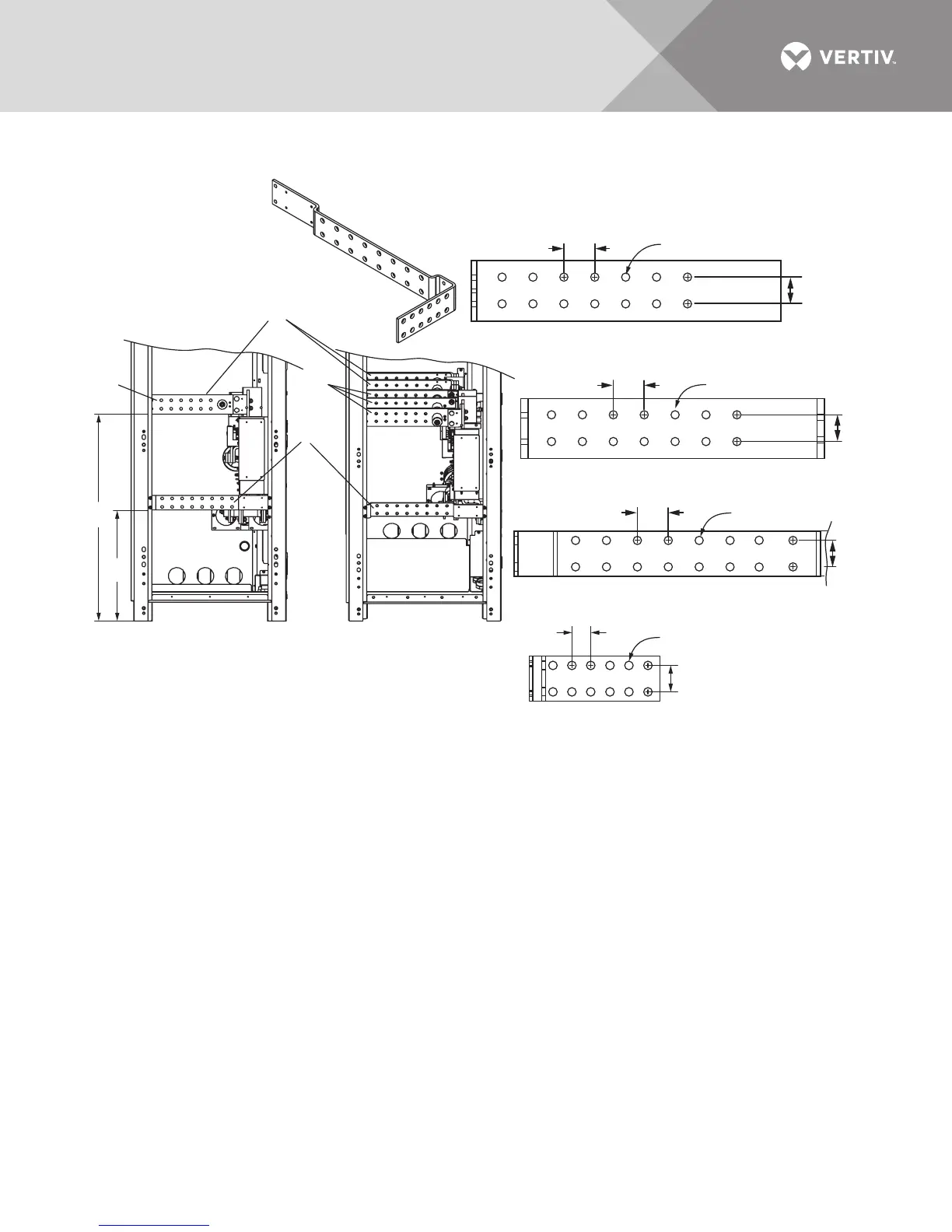
Notes
1. All dimensions are in inches (mm).
2. Control wiring and power wiring must be run in
separate conduits.
3. All wiring is to be in accordance with national and local electrical codes.
4. Based on NEC 408.56 minimum spacing, all live parts, including lugs, must be at
least 1" (25mm) from any other live part from a different phase or the
chassis frame. If lug stacking is required, the method of stacking and
required minimum spacing are the responsibility of the installing contractor
and authority having jurisdiction.
LEFT SIDE VIEW
INPUT
ISOMETRIC
VIEW
LEFT SIDE VIEW
TILTED DOWN
TO SHOW BUSBARS
U46-8E-3200B
Rev. 3
#1 Input Phase Busbar 20.5 x 4 x .38
#3
#3
#2 DC Pos. / Neg. Busbar 20.1 x 4 x .5
#3 Input Ground Busbar 25.4 x 3 x .25
(See Isometric View)
23
(584)
42.8
(1088)
#1 #1
#2
1.75
(44)
1.75
(44)
SE-556101