12 iGrowSeries 100 Installation Manual 960-0001-20
Equipment Installation
The iPonic 600
has eight (8) 115 VAC electrical outlets, a resettable 15 ampere fuse and a six foot
power cord. On each side of the unit the bottom two outlets are ganged, as shown in the Fig.5.2 below,
whereas, the top two are independent. This gives a total of six outputs that can be controlled
independently. These outputs are numbered from 1-3 on the left side from top to bottom and 4-6 on the
right side, also from top to bottom. In a typical installation, the equipment are connected as follows:
Output 1 – Lights
Output 2 – CO2 injector
Output 3 – Irrigation pump
Output 4 – Dehumidifier
Output 5 – Heater
Output 6 – Vent Fan(s)
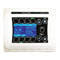
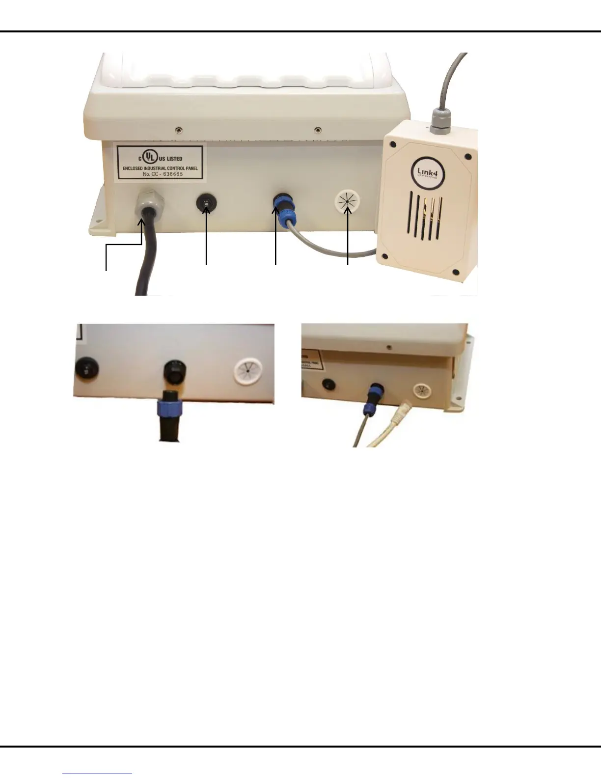
Resettable
Module
Ethernet
Connection
(Optional)
Fig 5.1 Sensor Module and Ethernet Connections