960-0001-20 iGrowSeries 100 Installation and User Manual 13
Warning: The total amperage drawn from the iPonic 600
must not exceed 15 amps.
Low Voltage Output Installation
Your iPonic 600™ has two (outputs #7 and #8) relays that are provided as dry contacts, i.e. switch
closures. If an output is activated to ON, the switch is “closed” (shorted); and if it is activated to OFF, the
switch is “open” (no continuity between the positive and negative terminals).
The board mounted relays are intended as “pilot” relays. For most loads you will want the iPonic 600™
outputs to control a load relay or contactor that is connected to the motor. However, in some cases such
as and alarm unit or irrigation valves that are 24 VAC, you can drive them directly assuming that you are
wiring only one or two valves per relay. The maximum current load recommended for each of the iPonic
600™ relays is 1.0 amp.
Warning – Do not exceed 1 Ampere or 24 Volts for outputs 7 and 8
Figure below shows the low voltage connection points for outputs 7 and 8.
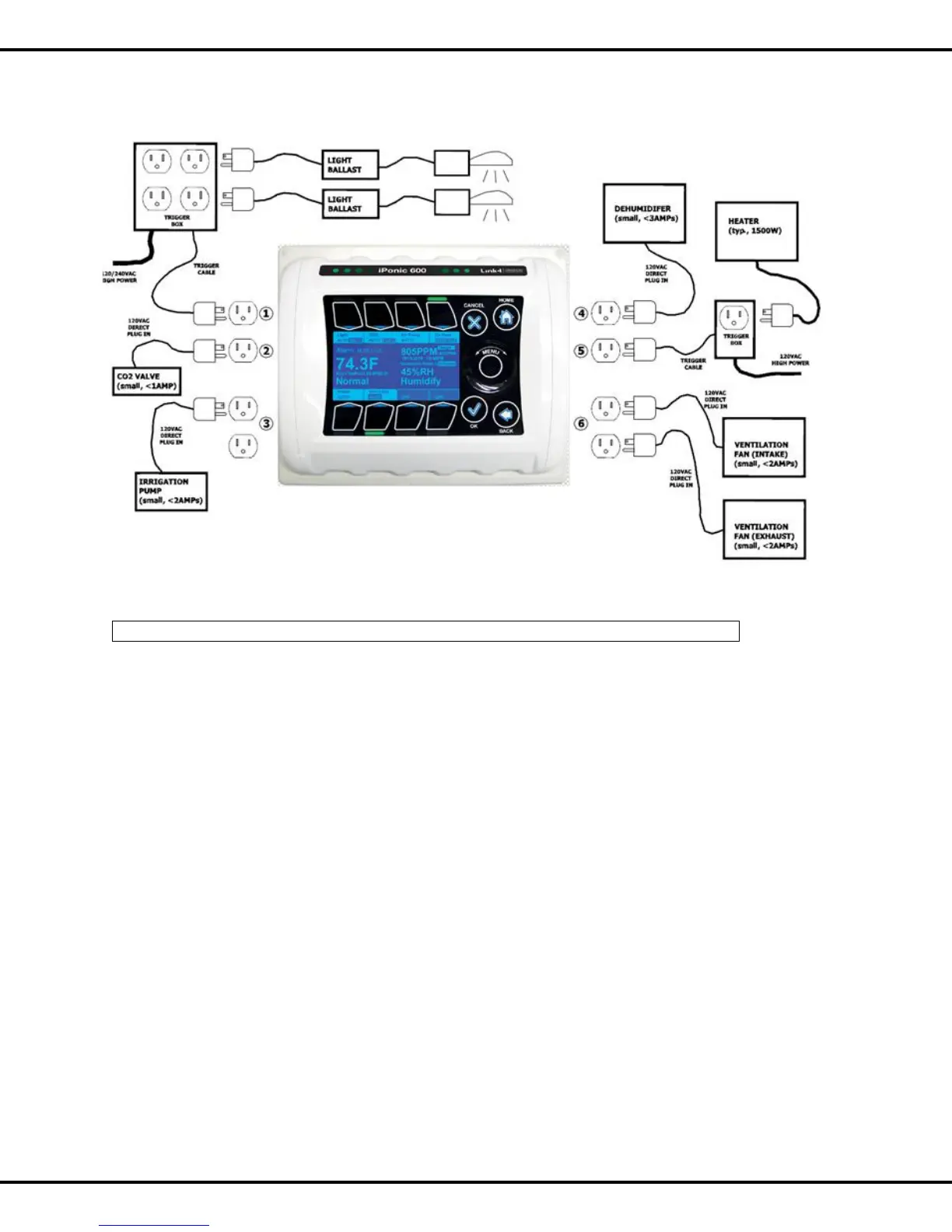
5.2 Equipment Installation