44 iGrowSeries 100 Installation Manual 960-0001-20
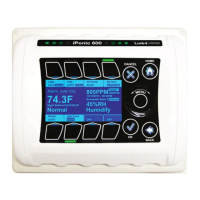
4.3.1.1 Map Sensors
The mapping of the inputs to the different sensors is done
here. The figure below shows the different inputs available for
mapping.
InTemp: Inside Temperature sensor
In Hum: Inside Humidity sensor
Light: Light sensor
OutTemp: Outside temperature sensor
Wind: Wind direction and speed sensor
Rain: Rain sensor
Back up Temp: Back up temperature sensor
On selecting a given input you are presented with options to
map that input to different sensors. You can also
enable/disable that sensor.
E.g. if are you are using an analog probe to measure the
inside temperature then select analog for In- Temp. If you
don‟t have a particular sensor selects None/Disabled for that
sensor.
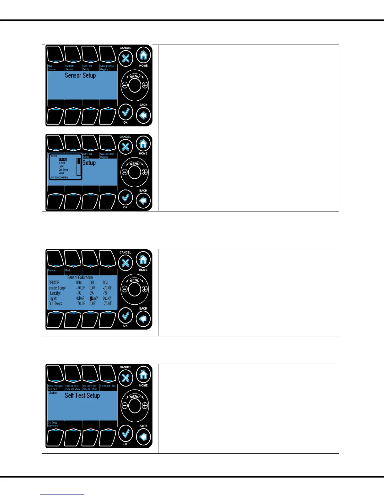
4.3.1.2 Calibrate Sensors
To calibrate an input the sensor is selected. The Previous
and Next buttons are used to scroll through the different
sensors.
Raw Value: This is the direct reading from the sensor.
CAL: This is the offset which will be added to raw value to
generate the adjusted value (ADJ). The Wheel can be used to
increase and decrease the values.
ADJ: This is the value which will be reflected on the status
screen.
4.3.1.3 Self-Test Set Up
This section enables the user to set up the test parameters for
automatic testing of the digital temperature sensors.
If a digital sensor is present and automatic testing of that
sensor is desired, map the sensor to one of the digital values
in the Map Sensors screen.
Note: This section only applies to mapped digital sensors.
Enable/Disable Test: Sets the test to enabled or disabled.
Button #1 is used to go to this option