960-0001-20 iGrowSeries 100 Installation and User Manual 19
Note that the display area itself is not touch sensitive.
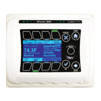
The main status screen displays the current status of your hydroponic growth room compartment. The numbers
shown are only sample numbers and will differ for each user, but a description for each display will be explained.
Normal – This is the current temperature stage. It can go from Cool 6, to Normal, to Heat 2.
Night SetPoint –.This is the current setpoint, normal stage. For this both the lower and upper
setpoints are shown, respectively. For heating or cooling stage, it will be the heat or cool setpoint
The large 72.3F is the current indoor temperature reading from the indoor temperature probe.
Humidity – This is the current relative humidity reading in the zone.
850 PPM – This is the current CO2 level, Whereas 1500 PPM fives the target CO2 level to be
obtained
Alarm Indicators – This shows which type of alarm is set. In the above case Humidity Low and
Co2 low have been set.
G-Curve – This shows that the growth schedule is active. It also shows the growth week in this
case i.e., 5
Light turn on delay is shown when the light bank is in the cooling period and it needs to turn on.
Fancut is shown Vent Fans are ON. In this case the CO2 pump is switched off.
For each of the outputs, the equipment‟s name is displayed, as well as the current controlled state that it is in:
o AUTO – equipment is being automatically controlled by the iPonic controller
o OFF – equipment is being manually FORCED to OFF.
o ON – equipment is being manually FORCED to ON.
o If the current state is highlighted it means that that output is switched ON.
The software output override can be activated by touching the respective button above/below the channel.
The controller also has manual mechanical override switches inside the unit. These switches need to be
in the AUTO position. If they are used to force the output OFF or ON, they will override all software
settings.