LS SERIES SERVICE MANUAL
ISSUE 4.0 POWER SUPPLIES 2
A stable +12V is required as a reference voltage for the motor over-current monitor circuit. This
voltage is provided by feeding the motor supply voltage to zener diode (D6) and resistor (R4). Note
that the Power LED (DS1) will light when the +12V supply is present.
The +5V supply from the Main PCB is used for the EEPROM IC1.
The PWM Driver IC, over-current monitor circuit and CMOS logic are all fed from another +12V
supply. This voltage is provided by reducing the +15V supply from the Main PCB using the 12V
regulator REG2.
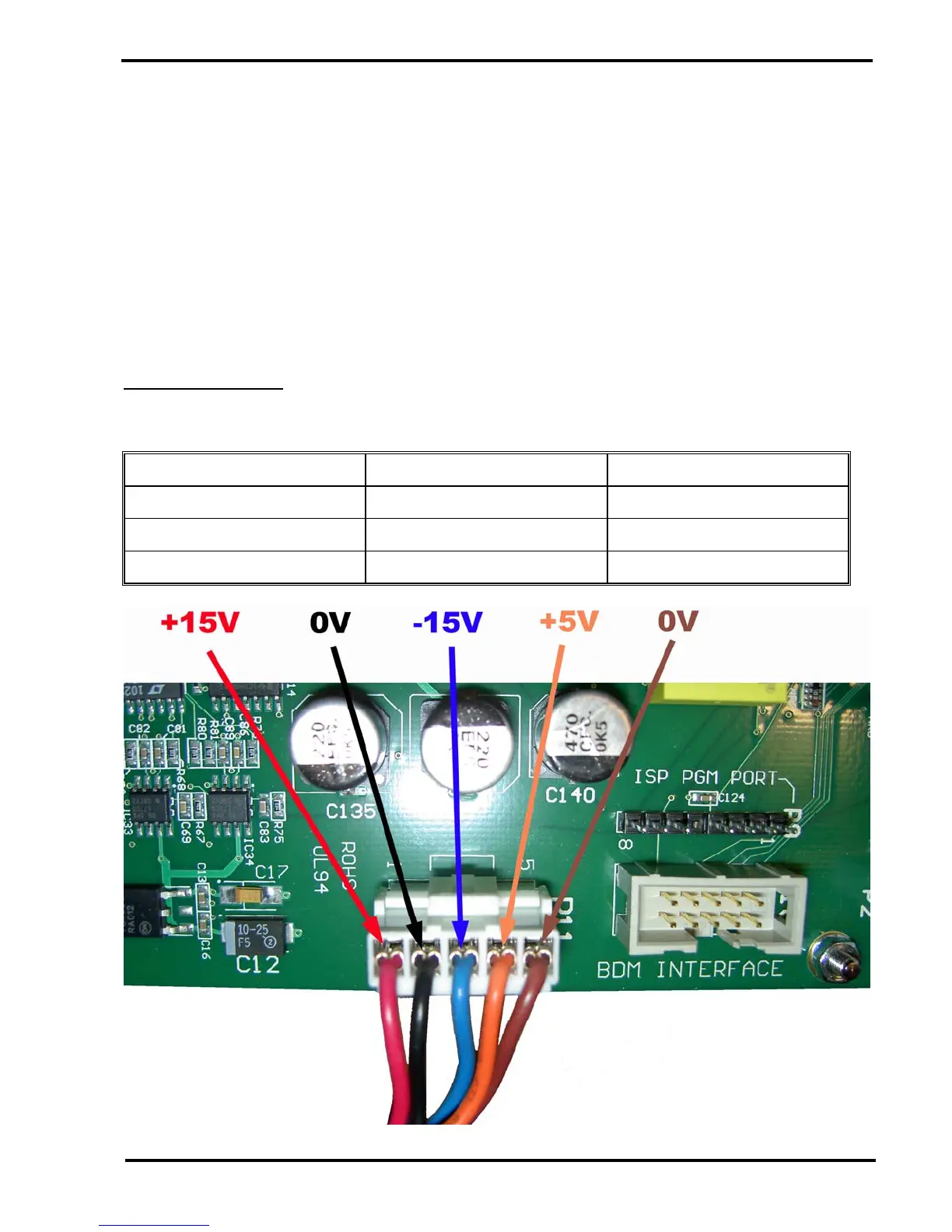
The voltages may be measured as shown in the tables below: -
Main PCB Supplies
Measure the power supplies on connector P11 - Use chassis as ground.
DC VOLTAGE MEASUREMENT POINT WIRE COLOUR
+5V Pin 4 Orange
+15V Pin 1 Red
-15V Pin 3 Blue