LS SERIES SERVICE MANUAL
ISSUE 4.0 POWER SUPPLIES 3
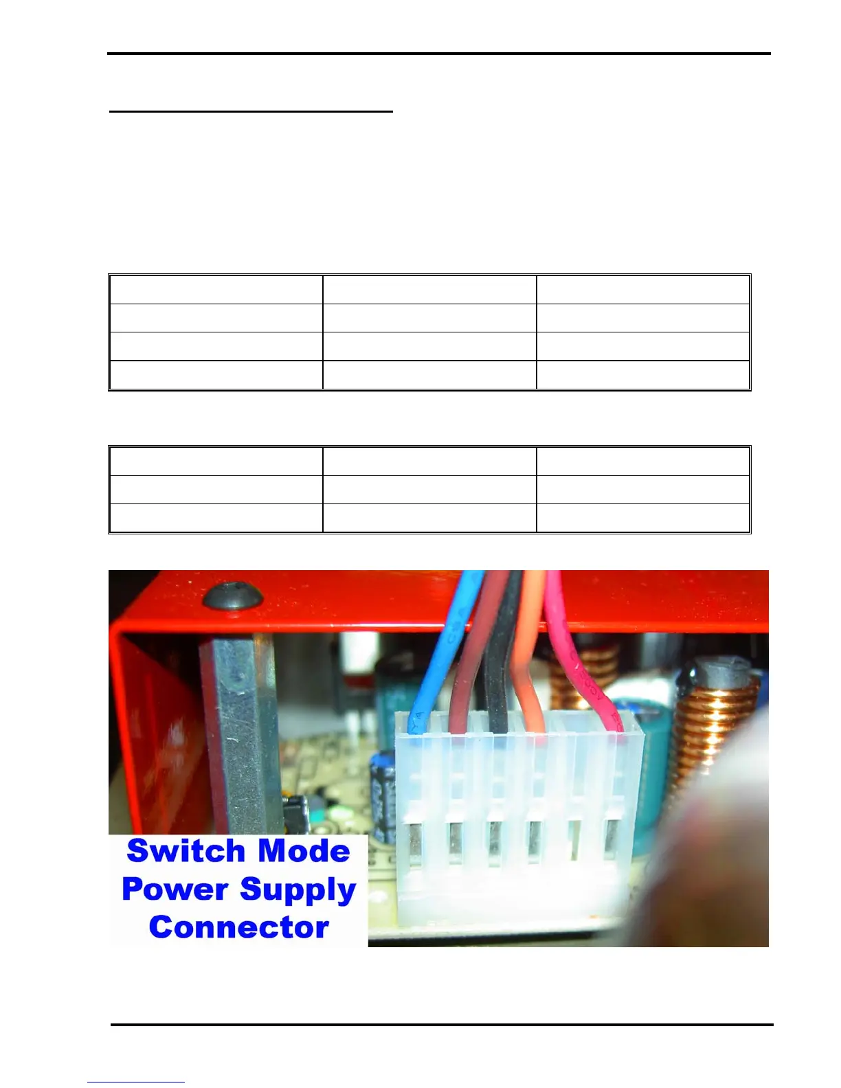
Switch Mode Power Supply Connector
The switch mode power supply is connected directly to P11 on the Main PCB so the voltages
can be measured there as shown above. However, if the Main PCB is suspected of excessively
loading the power supply, the connector can be removed from P11 on the Main PCB and the
voltages measured directly on the power supply connector as shown below: -
Measure the power supplies on the 6-way connector - Use Black or Brown wire as ground.
DC VOLTAGE MEASUREMENT POINT WIRE COLOUR
+5V Pin 3 Orange
+15V Pin 1 Red
-15V Pin 6 Blue
Ground Connections
DC VOLTAGE MEASUREMENT POINT WIRE COLOUR
0V Pin 4 Black
0V Pin 5 Brown