4.1.4 Serial ports
Alpha-Log provides four serial ports for the communication with external devices: two RS-232 (Com1 and
Com2), one RS-485 (Com3) and one TTL (Com4), to be used as follows:
• Com1(5): for the connection to 3G/4G modem only.
• Com2(6): for the connection to Modbus RTU devices with RS-232 output (e.g. the ALIEM Input
extension module) and to the PC (reserved to LSI LASTEM staff).
• Com3(10) (Fig. 2): for the connection to Modbus RTU devices with RS-485 output. Devices with RS-
232 output (including ALIEM) can be connected to this port through the dedicated RS-232/RS-485
serial converter.
• Com4(10) (Fig. 2): for the connection some of LSI LASTEM’s serial sensors.
They shall be set compatible with the devices in use.
To configure the serial ports for the modem and the PC, select Serial ports of 3DOM’s System parameters
section.
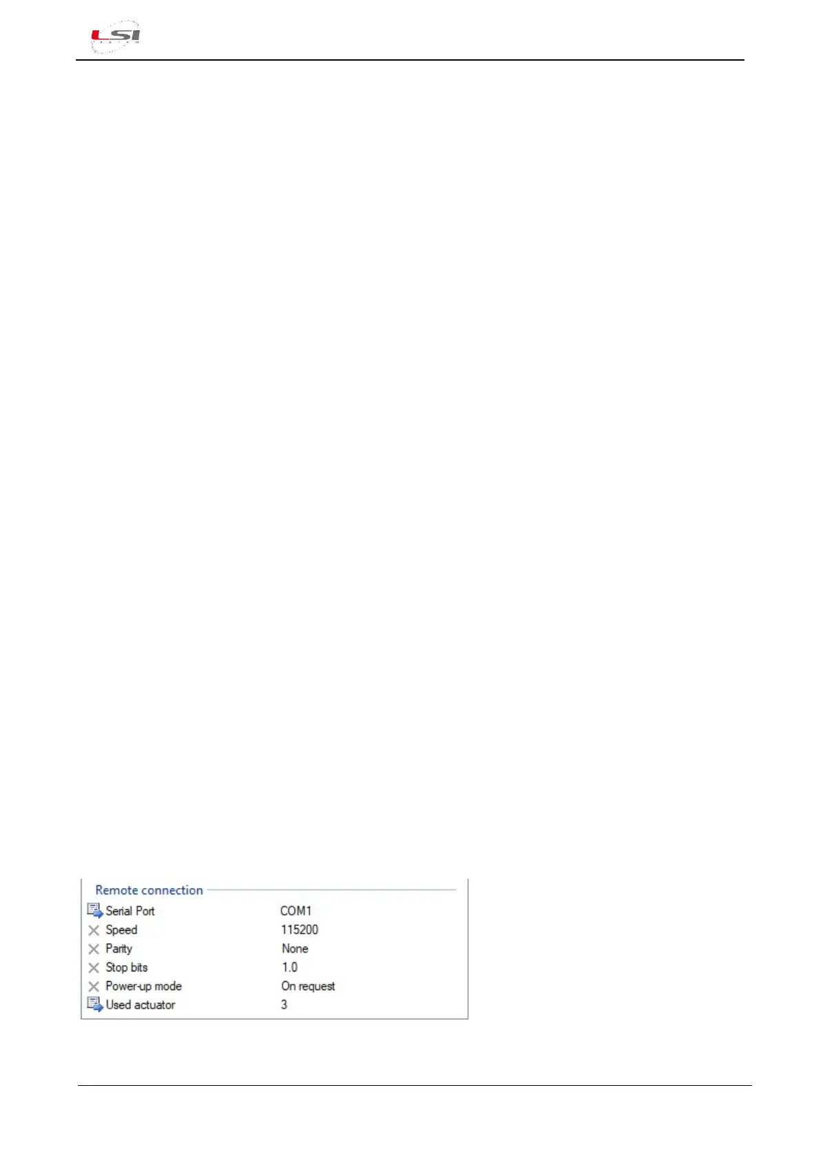
For the connection to the modem, configure Remote connection, by specifying:
➢ Serial port: is the serial port to connect the modem to. Select COM1. Default value: not used.
➢ Speed: is the speed Alpha-Log communicates with the modem. Select the same communication
speed set in the modem. Default value: 38400 bps.
➢ Parity: parameter used in the communication. It’s the same one set in the modem. Default value:
none.
➢ Stop Bit: parameter used in the communication. It’s the same one set in the modem. Default value:
1.
➢ Switch-on mode: expresses the mode the modem is turned on. It’s possible to choose between three
different types:
• On request: modem is turned on only in case of new data or alarms transmission by Alpha-
Log and is turned off when transmission is finalized. It is to be preferred in case of low power
functioning.
• Based on logic: modem is turned on according to a programmed logic (for example, from 1
PM to 4 PM every day). It is to be preferred in case of low power functioning in special
conditions.
• External power supply: modem’s switch-on does not depend on the data logger.
➢ Used actuator: set the number of the actuated output corresponding to the terminal block’ socket
where powering wires of the modem are connected. Output is typically PwrOut3 (§Fig. 2). Default
value: not used.
Fig. 13 – Remote port configuration example (modem).