➢ Lower threshold: it is the value of the lower threshold; it is not available when the More than logic
has been chosen.
➢ Hysteresis: it is a value that, depending on the type of comparison chosen, it is added or subtracted
from the threshold values, this will avoid continuous activation/deactivation of the logic, when the
measurement values are floating around the threshold.
➢ Minimum residence time outside: it is applied to a single measurement. It determines how long the
measurement must remain outside the limit for the logic activation.
➢ Minimum time of return within the limit: it is applied to a single measurement. It determines how
long the measurement must remain inside the limit for the logic deactivation.
4.1.9.2 Timer logic
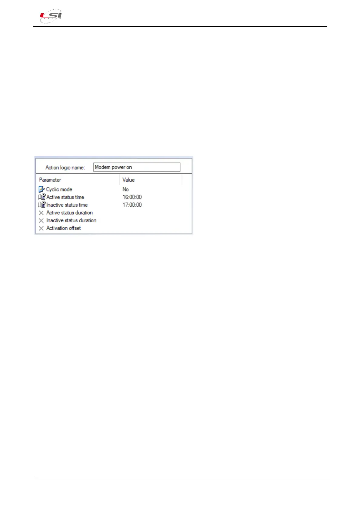
Fig. 17 it is an example of Timer logic.
Fig. 17 – Example of Timer logic.
It is possible to configure the following:
➢ Name of the logic: it is the name whom it will be reported on the messages SMS, Mail and MQTT.
➢ Cyclic mode:
• No: it indicates that the logic is active every day within the period of time from Active status
time to Inactive status time.
• Yes: it indicates that the logic switches on and off cyclically for the time periods specified in
Active status duration and Inactive status duration respectively. It is possible to specify an
activation delay by setting the Activation offset parameter.
Note that this logic can be combined with other logics in AND mode to allow, for example, the activation of
alarms or switched power outputs only at specific times of the day.