Installation 37
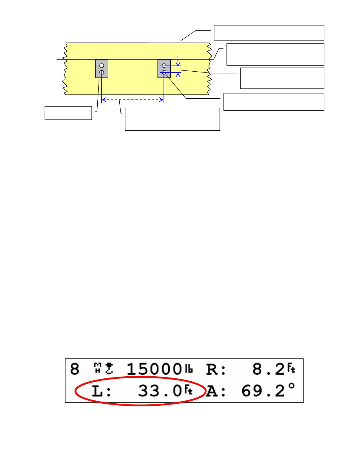
2. Mount the welding tabs. They must be placed parallel to each other, with 16 ⅛ inches between
the holes’ centres. Install the tabs such that they create a level mounting position in line with
the boom at 0 degrees.
Tip: When factory installed the GS011 angle/length sensor transmitter is integrated to the LS101
cable reel with the angle sensor zeroed. If the cable reel is installed perfectly level on the boom at
0 degrees, the angle sensor of the GS011 will also be zeroed. Minor adjustments to the angle
sensor (within plus or minus two degrees) are possible after cable reel installation.
3. Attach the reel to the welding tabs with the bolts provided. The reel should be orientated with
the GS011 angle/length sensor antenna coming out the top side of the cable reel cover.
4. Install the first cable guide (PA111) about 10 feet (3 metres) from the cable reel. Correct
alignment of the first guide is critical to ensure orderly winding of the cable on the reel. Install
the other guides at the end of each of the intermediate sections and the anchor (PA113) at the
end of the last section. All guides must be aligned so as to permit unobstructed movement of
the cable.
5. Pull out at least 5 feet (1 ½ metres) of cable, but not more than half the excess extension D.
Feed through the cable guides and attach to the cable anchor on the tip of the last boom sec-
tion. If additional cable length is required to reach the cable anchor point remove winds from
the reel without putting additional tension on the cable reel spring. There should be minimal
tension on the cable reel spring when the boom is fully retracted.
6. Verify the boom length indicated on the GS550 LCD. Boom length is indicated following the
length abbreviation “L”, typically on the first or second operation page. Boom length indicated
should equal the actual total boom length. The actual boom length is the distance from the
boom base pin to the head sheave centre as measured along the boom centreline. Depending
on the exact placement of the cable reel and the cable anchor the displayed length may differ
from the actual length.
Figure: GS550 LCD – typical operation page two with boom length indication
Boom base →
← Boom tip
Welding pads level and in line
with the boom at 0 degrees
Welding pad
Welding pad holes tapped ⅜-16
Welding pad holes 2 ¼ in.
apart, centre to centre
Boom at 0 degrees from horizontal
Welding pads holes 16 ⅛ in.
apart, centre-to-centre
Figure: Cable reel mounting positio
SkyAzúl, Equipment Solutions