Page 8-50 LTV
®
1200/1150 Ventilator Service Manual p/n 18603-001, Rev. C
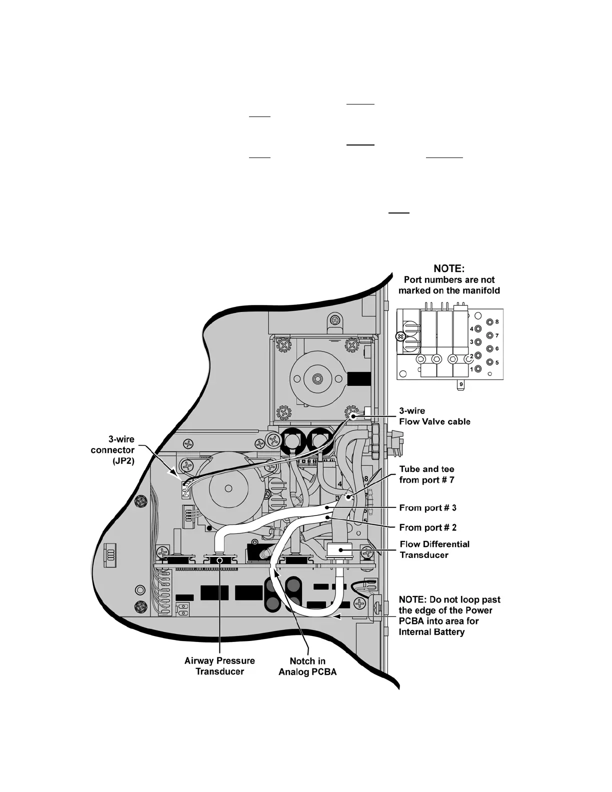
Final Tubing and Cable Installation:
1) Route the tube from Solenoid Manifold port # 3 under
the tube and tee attached to
Solenoid Manifold port # 7, over
previously installed tubing and onto the Airway
Pressure Transducer port, as shown.
2) Route the tube from Solenoid Manifold port # 2 under
the tube and tee attached to
Solenoid Manifold port # 7, over
the previously attached tubing, through the notch
in the Analog PCBA and onto the Flow Differential Transducer port, as shown.
• do not loop past the edge of the Power PCBA into the area for the Internal
Battery
3) Route the 3-wire, Flow Valve cable from the Flow Valve over
previously installed
tubing and the Accumulator. Attach the connector to the 3-wire connector (JP2) on
the Power PCBA, as shown.
The connector is keyed to fit only one way and will snap
into place when properly aligned.