p/n 18603-001, Rev. C LTV
®
1200/1150 Ventilator Service Manual Page 8-51
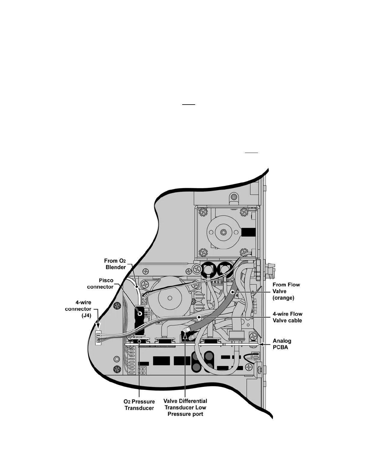
4) Attach the Pisco connector onto the O
2
Pressure Transducer port on the Analog
PCBA, as shown (LTV
®
1200 only).
5) Insert the tube from the O
2
Blender straight into the top of the Pisco connector (at
least 1/2”), as shown (LTV
®
1200 only).
• gently pull the Pisco connector (~2-lbs force) while holding the Analog
PCBA in place, then pull the tube while holding the Pisco connector to
ensure they are both properly attached
6) Route the 4-wire Flow Valve cable over
previously installed tubing and attach the
connector to the 4-wire connector (J4) on the Motor PCBA, as shown.
The
connector is keyed to fit only one way and will snap into place when properly aligned.
• for clarity, a warning label (“WARNING, DO NOT DISCONNECT WHILE
UNIT IS ON!”) attached to the 4-wire cable is intentionally not shown in the
following illustration
7) Route the orange tube (with elbow) from the Flow Valve over
previously installed
tubing and onto the Valve Differential Transducer Low Pressure port, as shown.