Page 8-52 LTV
®
1200/1150 Ventilator Service Manual p/n 18603-001, Rev. C
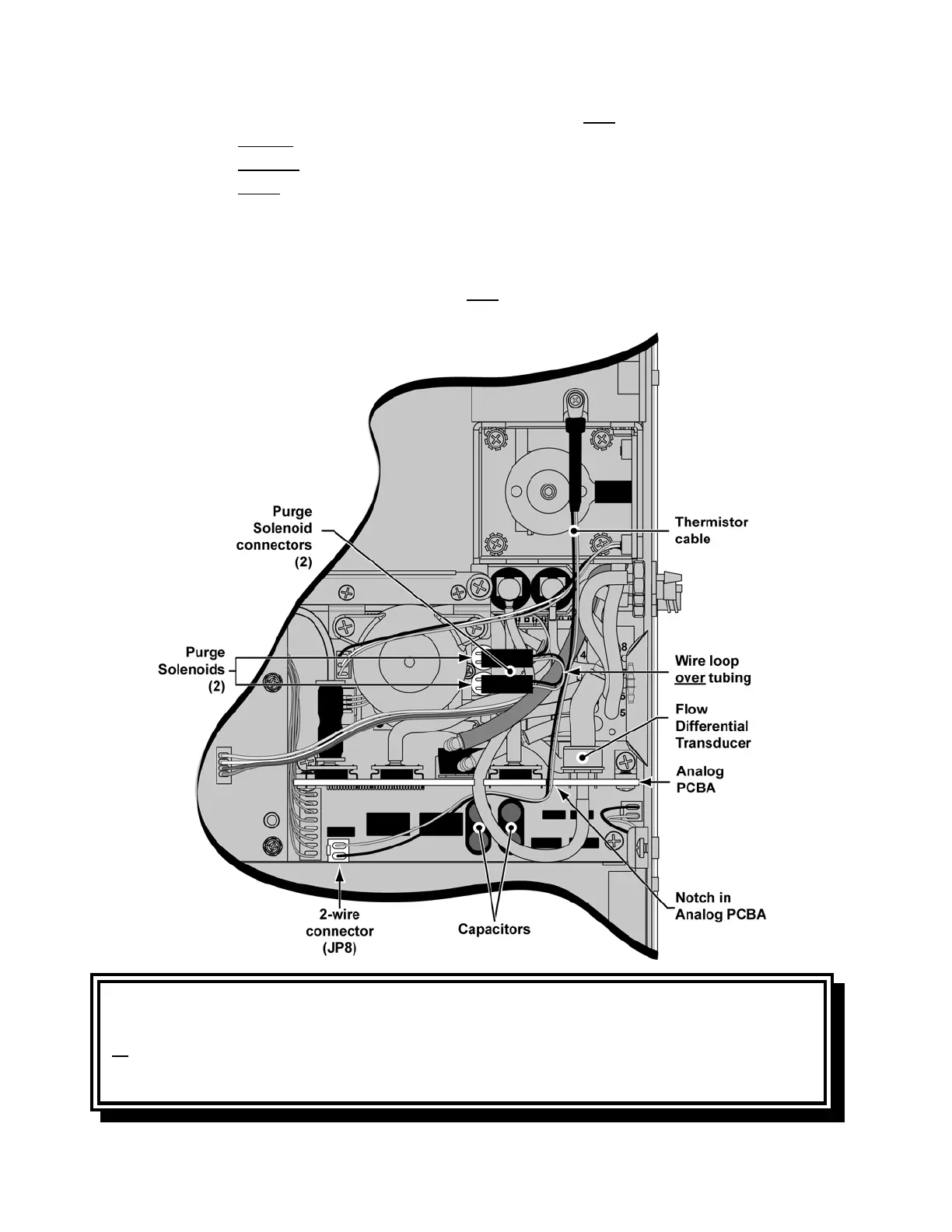
8) Route the 2-wire, Thermistor cable from the Flow Valve over previously installed tubing,
• through the notch in the Analog PCBA,
• between the Analog PCBA and the capacitors on the Power PCBA and
• under the tube attached to the Flow Differential Transducer.
Attach the connector to the 2-wire connector (JP8) on the Power PCBA, as shown.
The connector is keyed to fit only one way and will snap into place when properly
aligned.
9) Attach the Purge Solenoid connectors (2) onto the Purge Solenoids (either connector
onto either solenoid), with the wire loop over
previously installed tubing, as shown.
• hold the Purge Solenoids in-place while attaching the cable connectors
CAUTION
Final Tubing Check - Anytime internal flexible tubing is removed or replaced, check to ensure
all tubes have been correctly routed (point to point and layering), are fully connected on the ports
or fittings, and do not have any holes or tears in them. If necessary, gently reposition the tubing
to eliminate possible kinks or occlusions.